Nissan Qashqai (2007-2010). Manual — part 926
HAC-64
< COMPONENT DIAGNOSIS >
[AUTOMATIC AIR CONDITIONER]
BLOWER MOTOR
9.
CHECK BLOWER MOTOR FEEDBACK SIGNAL
1.
Reconnect fan control amp. connector.
2.
Turn ignition switch ON.
3.
Turn fan control dial to 1st speed.
4.
Check voltage between auto amp. harness connector M53 terminal 18 and ground.
Is the inspection result normal?
YES
>> Replace auto amp.
NO
>> Repair harness or connector.
10.
CHECK POWER VOLTAGE OF BLOWER RELAY
1.
Turn ignition switch OFF.
2.
Remove blower relay. Refer to
PG-110, "Fuse, Connector and Terminal Arrangement"
.
3.
Turn ignition switch ON.
4.
Check voltage between blower relay fuse block terminals 1, 3 and body ground. Refer to
for relay terminal assignment.
Is the inspection result normal?
YES
>> GO TO 12.
NO
>> GO TO 11.
11.
CHECK IGNITION SWITCH CIRCUIT
Check ignition switch circuit. Refer to
LOCK),
DLK-355, "Diagnosis Procedure"
(WITH I-KEY & SUPER LOCK),
DLK-597, "Diagnosis Procedure"
(WITHOUT I-KEY, WITHOUT SUPER LOCK) or
DLK-757, "Diagnosis Procedure"
SUPER LOCK).
Is the inspection result normal?
YES
>> Repair harness or connector.
NG
>> Replace malfunctioning parts.
12.
CHECK BLOWER RELAY
1.
Turn ignition switch OFF.
2.
PG-110, "Fuse, Connector and Terminal Arrangement"
3.
Check operation sound of the blower relay after switching ignition switch ON.
Is the inspection result normal?
YES
>> GO TO 13.
NO
>> Replace blower relay.
13.
CHECK FUSE
Check 15A fuse [Nos 15 and 16, located in the fuse block (J/B)]. Refer to
PG-110, "Fuse, Connector and Ter-
.
Is the inspection result normal?
YES
>> Repair harness or connector.
NG
>> Replace fuse.
14.
CHECK CIRCUIT CONTINUITY BETWEEN BLOWER MOTOR AND FAN CONTROL AMP.
(+)
(
−
)
Voltage
Auto amp.
—
Connector
Terminal
M53
18
Ground
Battery voltage
(+)
(
−
)
Voltage
Blower relay
—
1
Ground
Battery voltage
3
BLOWER MOTOR
HAC-65
< COMPONENT DIAGNOSIS >
[AUTOMATIC AIR CONDITIONER]
C
D
E
F
G
H
J
K
L
M
A
B
HAC
N
O
P
1.
Turn ignition switch OFF.
2.
Disconnect fan control amp. connector.
3.
Check continuity between blower motor harness connector M312 terminal 2 and fan control amp. harness
connector M311 terminal 1.
Is the inspection result normal?
YES
>> Replace blower motor.
NO
>> Repair harness or connector.
15.
CHECK CIRCUIT FAN CONTROL AMP.
Check continuity between fan control amp. harness connector M311 terminal 3 and 2.
Is the inspection result normal?
YES
>> Replace auto amp.
NO
>> Replace fan control amp.
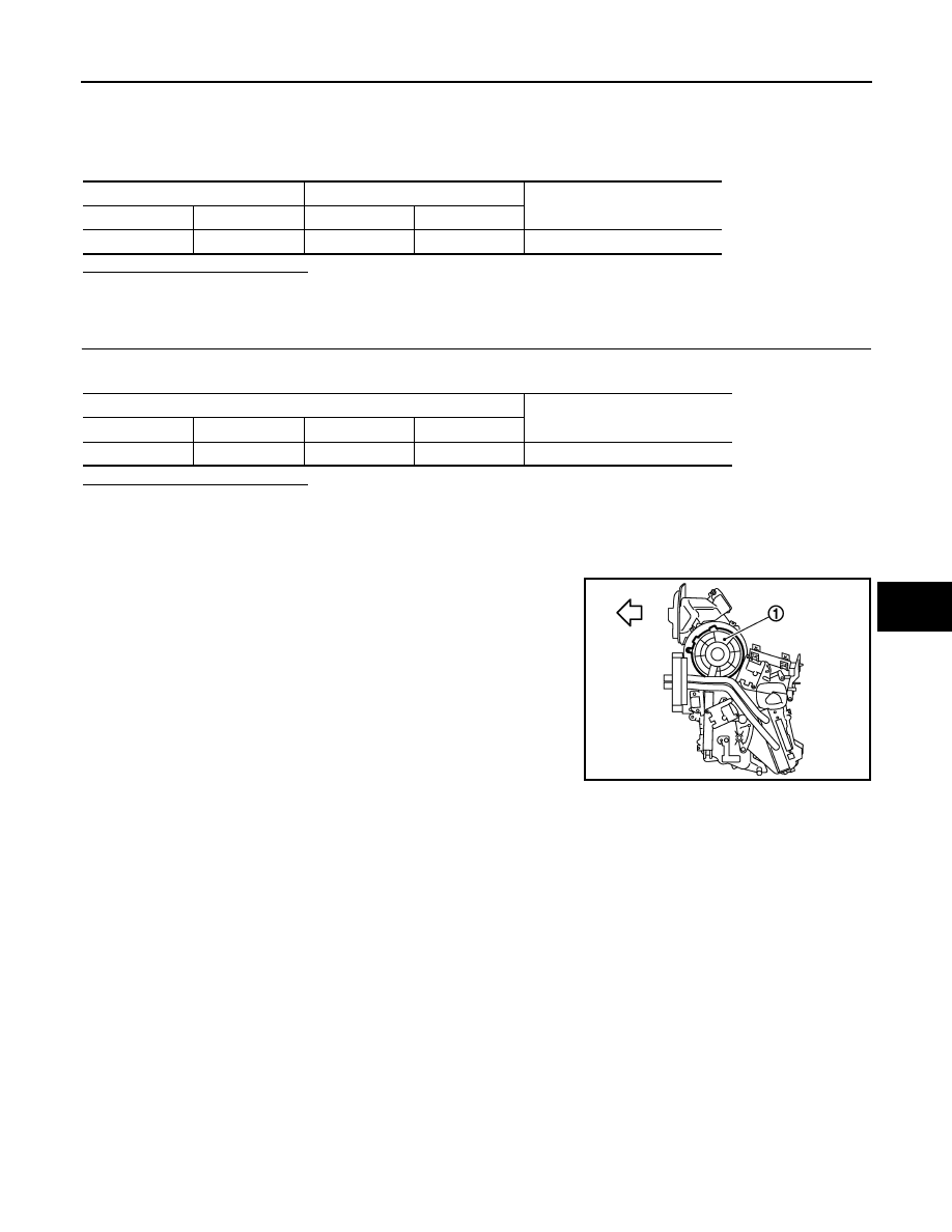
Component Inspection
INFOID:0000000000954655
Confirm smooth rotation of the blower motor (1).
Blower motor
Fan control amp.
Continuity
Connector
Terminal
Connector
Terminal
M312
2
M311
1
Continuity should exist
Fan control amp.
Continuity
Connector
Terminal
Connector
Terminal
M311
3
M311
2
Continuity should exist
:
Vehicle front
JPIIA0028ZZ

HAC-66
< COMPONENT DIAGNOSIS >
[AUTOMATIC AIR CONDITIONER]
MAGNET CLUTCH
MAGNET CLUTCH
Description
INFOID:0000000000954656
Magnet clutch drives a compressor, by a signal of IPDM E/R.
Component Function Check
INFOID:0000000000954657
1.
CONFIRM SYMPTOM BY PERFORMING THE FOLLOWING OPERATIONAL CHECK
1.
Press AUTO switch and A/C switch.
2.
AUTO switch indicator will turn ON. Confirm that the magnet clutch engages (sound or visual inspection).
(Discharge air and blower speed will depend on ambient, in-vehicle and set temperatures.)
Does the magnet clutch operate?
YES
>> END.
NO
>> Go to Diagnosis Procedure. Refer to
.
Diagnosis Procedure
INFOID:0000000000954658
1.
PERFORM SELF-DIAGNOSIS STEP-2
Perform self-diagnosis STEP-2. Refer to
HAC-27, "Diagnosis Description"
, see No. 1 to 3.
Is there any malfunction displayed?
YES
>> Go to appropriate malfunctioning sensor circuit. Refer to
HAC-27, "Diagnosis Description"
, see to
No. 11.
NO
>> GO TO 2.
2.
PERFORM SELF-DIAGNOSIS STEP-4
Perform self-diagnosis STEP-4. Refer to
HAC-27, "Diagnosis Description"
, see No. 1 to 6.
Is it operated normally?
YES
>> END.
NO
>> GO TO 3.
3.
PERFORM AUTO ACTIVE TEST
Perform “AUTO ACTIVE TEST”. Refer to
PCS-9, "Diagnosis Description"
Does the magnet clutch operate?
YES
>> •
WITH CONSULT-III: GO TO 7.
•
WITHOUT CONSULT-III: GO TO 8.
NO
>> Check 10A fuse (No. 53, located in IPDM E/R), and GO TO 4.
4.
CHECK CIRCUIT CONTINUITY BETWEEN IPDM E/R AND COMPRESSOR
1.
Turn ignition switch OFF.
2.
Disconnect IPDM E/R connector and compressor connector.
3.
Check continuity between IPDM E/R harness connector E12 terminal 23 and compressor harness con-
nector F17 (With Gasoline Engine) or F18 (With Diesel Engine) terminal 1.
With Gasoline Engine
With Diesel Engine
Is the inspection result normal?
YES
>> GO TO 5.
NO
>> Repair harness or connector.
IPDM E/R
Compressor
Continuity
Connector
Terminal
Connector
Terminal
E12
23
F17
1
Continuity should exist
IPDM E/R
Compressor
Continuity
Connector
Terminal
Connector
Terminal
E12
23
F18
1
Continuity should exist
MAGNET CLUTCH
HAC-67
< COMPONENT DIAGNOSIS >
[AUTOMATIC AIR CONDITIONER]
C
D
E
F
G
H
J
K
L
M
A
B
HAC
N
O
P
5.
CHECK CIRCUIT CONTINUITY BETWEEN COMPRESSOR GROUND
Check continuity between compressor harness connector F17 (With Gasoline Engine) or F18 (With Diesel
Engine) terminal 2 and ground.
With Gasoline Engine
With Diesel Engine
Is the inspection result normal?
YES
>> GO TO 6.
NO
>> Repair harness or connector.
6.
CHECK MAGNET CLUTCH CIRCUIT
Check for operation sound when applying battery voltage direct current to terminal.
Is the inspection result normal?
YES
>> 1.
Replace IPDM E/R.
2.
Refer to self-diagnosis procedure
HAC-27, "Diagnosis Description"
and perform self-diagno-
sis STEP-4. Confirm that magnet clutch operation normal.
NO
>> 1.
Replace compressor.
2.
Refer to self-diagnosis procedure
HAC-27, "Diagnosis Description"
and perform self-diagno-
sis STEP-4. Confirm that magnet clutch operation normal.
7.
CHECK BCM INPUT (COMPRESSOR ON) SIGNAL
Check compressor ON/OFF signal in “DATA MONITOR”. Refer to
HAC-31, "CONSULT-III Function"
Is the inspection result normal?
YES
>> GO TO 11.
NO
>> GO TO 8.
8.
CHECK CIRCUIT CONTINUITY BETWEEN BCM AND AUTO AMP.
1.
Turn ignition switch OFF.
2.
Disconnect BCM harness connector and auto amp. harness connector.
3.
Check continuity between BCM harness connector M65 terminal 14 and auto amp. harness connector
M53 terminal 5.
Is the inspection result normal?
YES
>> GO TO 9.
NO
>> Repair harness or connector.
9.
CHECK BCM
1.
Connect BCM harness connector.
2.
Turn ignition switch ON.
3.
Check voltage between BCM harness connector M65 terminal 14 and ground.
Compressor
—
Continuity
Connector
Terminal
F17
2
Ground
Continuity should exist
Compressor
—
Continuity
Connector
Terminal
F18
2
Ground
Continuity should exist
A/C SW ON
: AIR COND SW ON
A/C SW OFF
: AIR COND SW OFF
BCM
Auto amp.
Continuity
Connector
Terminal
Connector
Terminal
M65
14
M53
5
Continuity should exist
Нет комментариевНе стесняйтесь поделиться с нами вашим ценным мнением.
Текст