Nissan Qashqai (2007-2010). Manual — part 928
HAC-72
< COMPONENT DIAGNOSIS >
[AUTOMATIC AIR CONDITIONER]
PTC HEATER
Is the inspection result normal?
YES
>> GO TO 3.
NO
>> Repair harness or connector.
3.
CHECK PTC HEATER-2 OPERATION
1.
Start engine.
2.
Select “PTC HEATER” of BCM active test item.
3.
With operating the item, check voltage between PTC heater harness connector E117 terminal 4 and
ground.
Is the inspection result normal?
YES
>> GO TO 4.
NO
>> GO TO 12.
4.
CHECK GROUND CIRCUIT FOR PTC HEATER-2
1.
Turn ignition switch OFF.
2.
Check continuity between PTC heater harness connector E116 terminal 2 and ground.
Is the inspection result normal?
YES
>> Replace PTC heater.
NO
>> Repair harness or connector.
5.
CHECK VOLTAGE FOR PTC RELAY-1
1.
Turn ignition switch OFF.
2.
Disconnect PTC relay-1.
3.
Turn ignition switch ON.
4.
Check voltage between PTC relay-1 harness connector E53 terminal 3 and ground.
Is the inspection result normal?
YES
>> GO TO 7.
NO
>> GO TO 6.
6.
CHECK FUSE
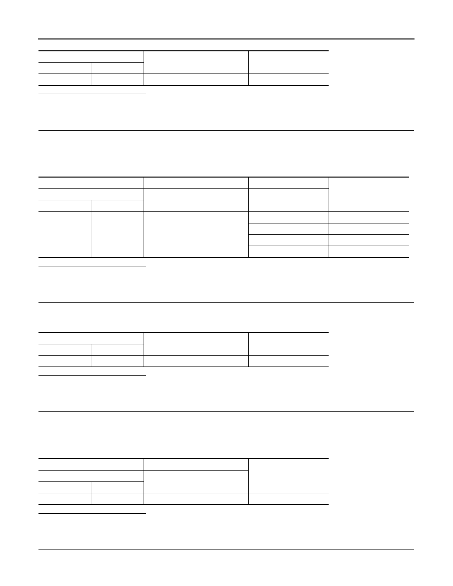
PTC heater
—
Continuity
Connector
Terminal
E116
1
Ground
Continuity should exist.
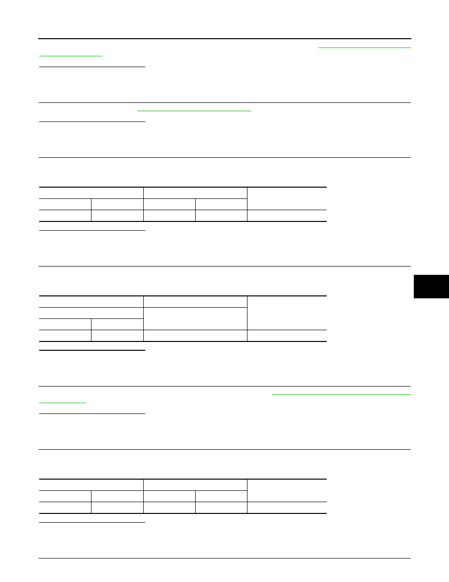
(+)
(
−
)
Test item
Voltage
PTC heater
—
PTC HEATER
Connector
Terminal
E117
4
Ground
OFF
Approx. 0
PTC 1
Approx. 0
PTC 2
Battery voltage
PTC 3
Battery voltage
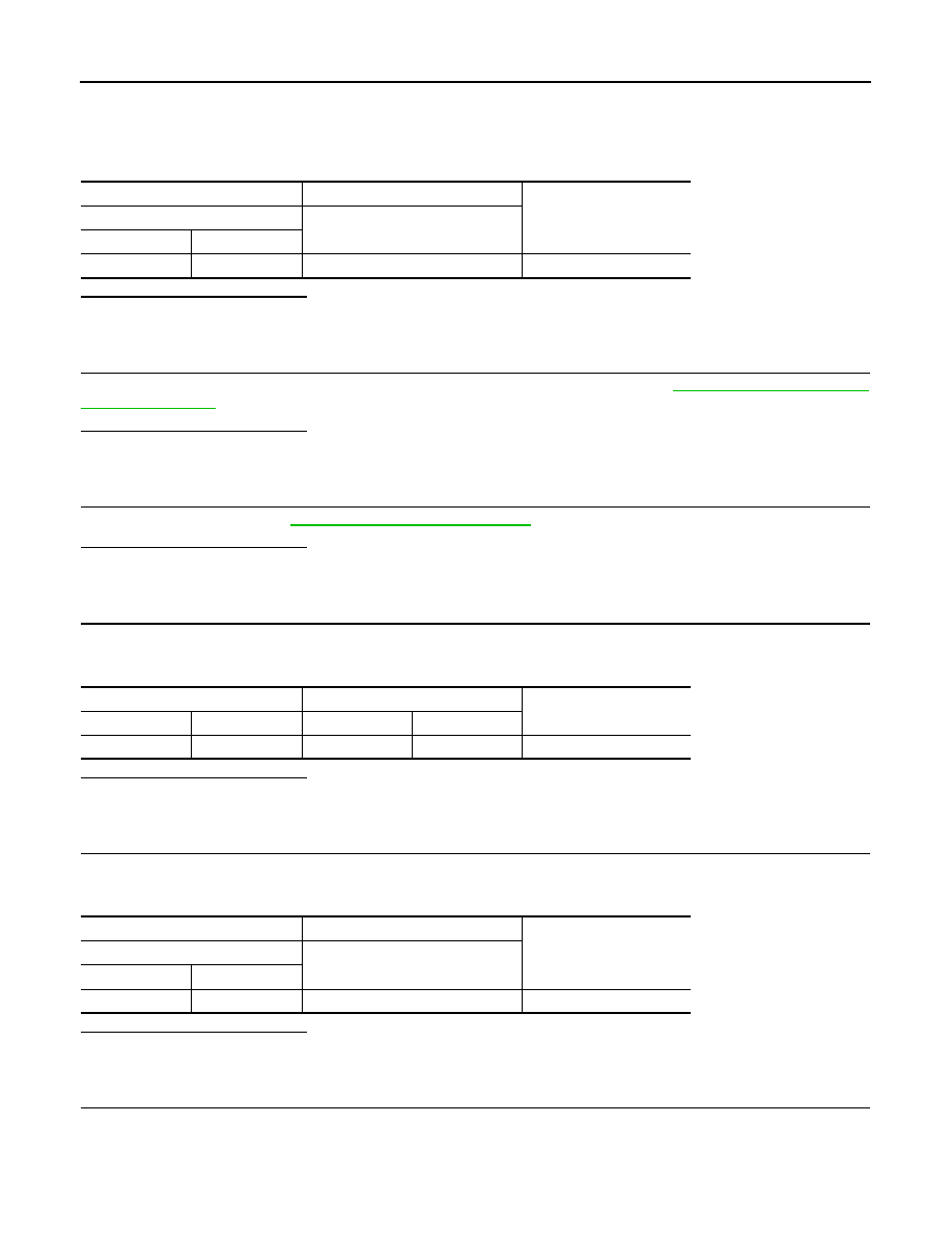
PTC heater
—
Continuity
Connector
Terminal
E116
2
Ground
Continuity should exist
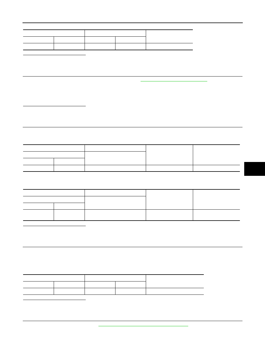
(+)
(
−
)
Voltage
PTC relay-1
—
Connector
Terminal
E53
3
Ground
Battery voltage
PTC HEATER
HAC-73
< COMPONENT DIAGNOSIS >
[AUTOMATIC AIR CONDITIONER]
C
D
E
F
G
H
J
K
L
M
A
B
HAC
N
O
P
Check 30A fuse (Nos 37, located in the fuse, fusible link and relay box). Refer to
Is the inspection result normal?
YES
>> Repair harness or connector.
NO
>> Replace the blown fuse after repairing the affected circuit if a fuse is blown.
7.
CHECK PTC RELAY-1
Check PTC relay-1. Refer to
HAC-76, "Component Inspection"
.
Is the inspection result normal?
YES
>> GO TO 8.
NO
>> Replace PTC relay-1.
8.
CHECK CIRCUIT CONTINUITY BETWEEN PTC RELAY-1 AND PTC HEATER
Check continuity between PTC relay-1 harness connector E53 terminal 5 and PTC heater harness connector
E117 terminal 3.
Is the inspection result normal?
YES
>> GO TO 9.
NO
>> Repair harness or connector.
9.
CHECK POWER SUPPLY FOR PTC RELAY-1
1.
Turn ignition switch ON.
2.
Check voltage between PTC relay-1 harness connector E53 terminal 1 and ground.
Is the inspection result normal?
YES
>> GO TO 11.
NO
>> GO TO 10.
10.
CHECK FUSE
Check 10A fuse [Nos 17, located in the fuse block (J/B)]. Refer to
PG-110, "Fuse, Connector and Terminal
.
Is the inspection result normal?
YES
>> Repair harness or connector.
NO
>> Replace the blown fuse after repairing the affected circuit if a fuse is blown.
11.
CHECK CIRCUIT CONTINUIT BETWEEN PTC RELAY-1 AND IPDM E/R
Check continuity between PTC relay-1 harness connector E53 terminal 2 and IPDM E/R harness connector
E11 terminal 11.
Is the inspection result normal?
YES
>> GO TO 18.
NO
>> Repair harness or connector.
12.
CHECK VOLTAGE FOR PTC RELAY-2
PTC relay-1
PTC heater
Continuity
Connector
Terminal
Connector
Terminal
E53
5
E117
3
Continuity should exist
(+)
(
−
)
Voltage
PTC relay-1
—
Connector
Terminal
E53
1
Ground
Battery voltage
PTC relay-1
IPDM E/R
Continuity
Connector
Terminal
Connector
Terminal
E53
2
E11
11
Continuity should exist
HAC-74
< COMPONENT DIAGNOSIS >
[AUTOMATIC AIR CONDITIONER]
PTC HEATER
1.
Turn ignition switch OFF.
2.
Disconnect PTC relay-2.
3.
Turn ignition switch ON.
4.
Check voltage between PTC relay-2 harness connector E54 terminal 3 and ground.
Is the inspection result normal?
YES
>> GO TO 14.
NO
>> GO TO 13.
13.
CHECK FUSE
Check 30A fuse (Nos 35, located in the fuse, fusible link and relay box). Refer to
Is the inspection result normal?
YES
>> Repair harness or connector.
NO
>> Replace the blown fuse after repairing the affected circuit if a fuse is blown.
14.
CHECK PTC RELAY-2
Check PTC relay-2. Refer to
HAC-76, "Component Inspection"
.
Is the inspection result normal?
YES
>> GO TO 15.
NO
>> Replace PTC relay-2.
15.
CHECK CIRCUIT CONTINUIT BETWEEN PTC RELAY-2 AND PTC HEATER
Check continuity between PTC relay-2 harness connector E54 terminal 5 and PTC heater harness connector
E117 terminal 4.
Is the inspection result normal?
YES
>> GO TO 16.
NO
>> Repair harness or connector.
16.
CHECK POWER SUPPLY FOR PTC RELAY-2
1.
Turn ignition switch ON.
2.
Check voltage between PTC relay-2 harness connector E54 terminal 1 and ground.
Is the inspection result normal?
YES
>> GO TO 17.
NO
>> GO TO 10.
17.
CHECK CIRCUIT CONTINUIT BETWEEN PTC RELAY-2 AND IPDM E/R
Check continuity between PTC relay-2 harness connector E54 terminal 2 and IPDM E/R harness connector
E11 terminal 12.
(+)
(
−
)
Voltage
PTC relay-2
—
Connector
Terminal
E54
3
Ground
Battery voltage
PTC relay-2
PTC heater
Continuity
Connector
Terminal
Connector
Terminal
E54
5
E117
4
Continuity should exist.
(+)
(
−
)
Voltage
PTC relay-2
—
Connector
Terminal
E54
1
Ground
Battery voltage
PTC HEATER
HAC-75
< COMPONENT DIAGNOSIS >
[AUTOMATIC AIR CONDITIONER]
C
D
E
F
G
H
J
K
L
M
A
B
HAC
N
O
P
Is the inspection result normal?
YES
>> GO TO 18.
NO
>> Repair harness or connector.
18.
CHECK BCM INPUT (FAN ON) SIGNAL
Check FAN ON/OFF signal in “DATA MONITOR”. Refer to
HAC-31, "CONSULT-III Function"
.
Is the inspection result normal?
YES
>> GO TO 21.
NO
>> GO TO 19.
19.
CHECK FAN ON SIGNAL
1.
Turn ignition switch ON.
2.
Check voltage between auto amp. harness connector M53 terminal 24 and ground.
3.
Turn fan control dial clockwise.
4.
Check voltage between auto amp. harness connector M53 terminal 24 and ground.
Is the inspection result normal?
YES
>> GO TO 20.
NO
>> Replace auto amp.
20.
CHECK CIRCUIT CONTINUITY BETWEEN BCM AND AUTO AMP.
1.
Turn ignition switch OFF.
2.
Disconnect BCM harness connector.
3.
Check continuity between BCM harness connector M65 terminal 15 and auto amp. harness connector
M53 terminal 24.
Is the inspection result normal?
YES
>> GO TO 21.
NO
>> Repair harness or connector.
21.
CHECK CAN COMMUNICATION
Check CAN communication. Refer to
LAN-59, "CAN Communication Signal Chart"
PTC relay-1
IPDM E/R
Continuity
Connector
Terminal
Connector
Terminal
E54
2
E11
12
Continuity should exist.
FAN CONTROL DIAL ON
: FAN ON SIG ON
FAN CONTROL DIAL OFF
: FAN ON SIG OFF
(+)
(
−
)
Condition
Voltage
Auto amp.
—
Connector
Terminal
M53
24
Ground
Fan control dial: OFF
Approx. 12
(+)
(
−
)
Condition
Voltage
Auto amp.
—
Connector
Terminal
M53
24
Ground
Fan control dial: ON
(Blower motor operates.)
Approx. 0
BCM
Auto amp.
Continuity
Connector
Terminal
Connector
Terminal
M65
15
M53
24
Continuity should exist
Нет комментариевНе стесняйтесь поделиться с нами вашим ценным мнением.
Текст