Nissan Qashqai (2007-2010). Manual — part 925
HAC-60
< COMPONENT DIAGNOSIS >
[AUTOMATIC AIR CONDITIONER]
INTAKE DOOR MOTOR
Is the inspection result normal?
YES
>> GO TO 5.
NO
>> Replace auto amp.
5.
CHECK SIGNAL FOR AUTO AMP.
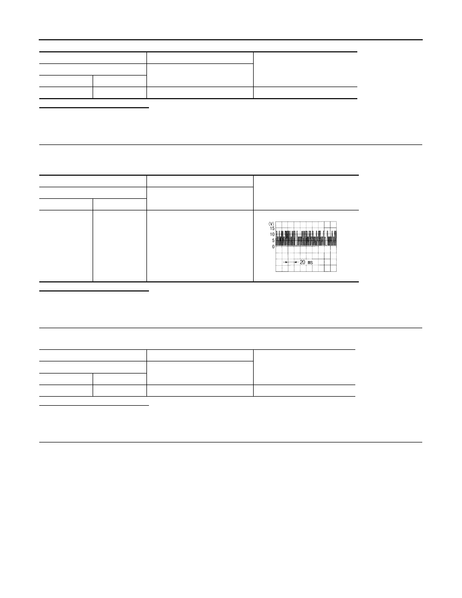
Confirm A/C LAN signal between auto amp. harness connector M53 terminal 3 and ground using an oscillo-
scope.
Is the inspection result normal?
YES
>> GO TO 6.
NO
>> Replace auto amp.
6.
CHECK POWER SUPPLY FOR INTAKE DOOR MOTOR
Check voltage between intake door motor harness connector M304 terminal 1 and ground.
Is the inspection result normal?
YES
>> GO TO 7.
NO
>> Repair harness or connector.
7.
CHECK SIGNAL FOR INTAKE DOOR MOTOR
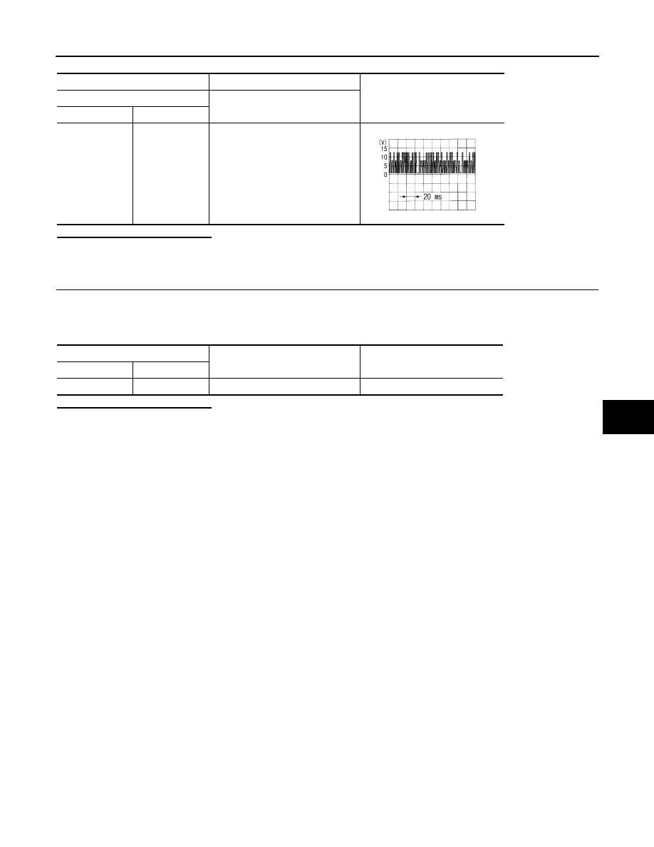
Confirm A/C LAN signal between intake door motor harness connector M304 terminal 3 and ground using an
oscilloscope.
(+)
(
−
)
Voltage
Auto amp.
—
Connector
Terminal
M53
20
Ground
Battery voltage
(+)
(
−
)
Voltage
Auto amp.
—
Connector
Terminal
M53
3
Ground
SJIA1453J
(+)
(
−
)
Voltage
Intake door motor
—
Connector
Terminal
M304
1
Ground
Battery voltage
INTAKE DOOR MOTOR
HAC-61
< COMPONENT DIAGNOSIS >
[AUTOMATIC AIR CONDITIONER]
C
D
E
F
G
H
J
K
L
M
A
B
HAC
N
O
P
Is the inspection result normal?
YES
>> GO TO 8.
NO
>> Repair harness or connector.
8.
CHECK INTAKE DOOR MOTOR GROUND CIRCUIT
1.
Turn ignition switch OFF.
2.
Disconnect intake door motor connector.
3.
Check continuity between intake door motor harness connector M304 terminal 2 and ground.
Is the inspection result normal?
YES
>> Replace intake door motor.
NO
>> Repair harness or connector.
(+)
(
−
)
Voltage
Intake door motor
—
Connector
Terminal
M304
3
Ground
SJIA1453J
Intake door motor
—
Continuity
Connector
Terminal
M304
2
Ground
Continuity should exist
HAC-62
< COMPONENT DIAGNOSIS >
[AUTOMATIC AIR CONDITIONER]
BLOWER MOTOR
BLOWER MOTOR
Description
INFOID:0000000000954652
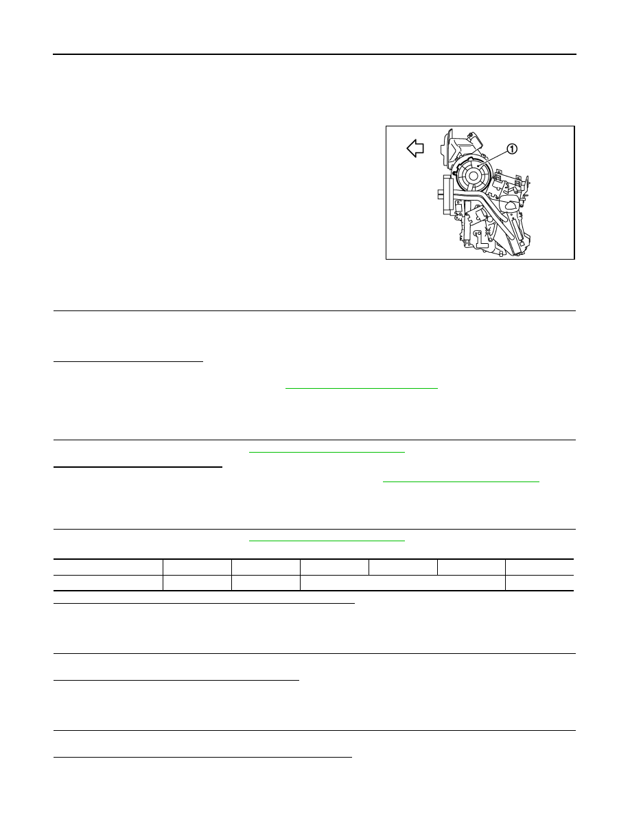
COMPONENT DESCRIPTION
The blower motor (1) utilizes a brush motor with a sirocco fan type.
Component Function Check
INFOID:0000000000954653
1.
CONFIRM SYMPTOM BY PERFORMING THE FOLLOWING OPERATIONAL CHECK
1.
Turn fan control dial clockwise. Blower should operate on low speed.
2.
Turn fan control dial clockwise, and continue checking blower speed and fan LEDs until all speeds
checked.
Is the inspection result normal?
YES
>> END.
NO
>> Go to diagnosis procedure. Refer to
Diagnosis Procedure
INFOID:0000000000954654
1.
PERFORM SELF-DIAGNOSIS STEP-2
Perform self-diagnosis STEP-2. Refer to
HAC-27, "Diagnosis Description"
, see No. 1 to 3.
Is there any malfunction displayed?
YES
>> Go to appropriate malfunctioning sensor circuit. Refer to
HAC-27, "Diagnosis Description"
, see to
No. 11.
NO
>> GO TO 2.
2.
PERFORM SELF-DIAGNOSIS STEP-4
Perform self-diagnosis STEP-4. Refer to
HAC-27, "Diagnosis Description"
, see No. 1 to 6.
Does blower motor speed change according to each code No.?
YES
>> GO TO 3.
NO
>> GO TO 5.
3.
CHECK ENGINE COOLANT TEMPERATURE
Check engine coolant temperature.
Is engine coolant temperature below 56
°
C (133
°
F)?
YES
>> GO TO 4.
NO
>> Blower motor operation is normal.
4.
CHECK BLOWER MOTOR OPERATING
Check blower motor operating.
Is blower motor operation under starting blower speed control?
YES
>> END.
NO
>> GO TO 5.
:
Vehicle front
JPIIA0028ZZ
Code No.
41
42
43
44
45
46
Blower motor voltage
5 V
11.75 V
8.5 V
11.75 V
BLOWER MOTOR
HAC-63
< COMPONENT DIAGNOSIS >
[AUTOMATIC AIR CONDITIONER]
C
D
E
F
G
H
J
K
L
M
A
B
HAC
N
O
P
5.
CHECK POWER SUPPLY FOR BLOWER MOTOR
1.
Disconnect blower motor connector.
2.
Turn ignition switch ON.
3.
Check voltage between blower motor harness connector M312 terminal 1 and ground.
Is the inspection result normal?
YES
>> GO TO 6.
NO
>> GO TO 10.
6.
CHECK POWER SUPPLY FOR FAN CONTROL AMP.
1.
Disconnect fan control amp. connector.
2.
Check voltage between fan control amp. harness connector M311 terminal 1 and ground.
Is the inspection result normal?
YES
>> GO TO 7.
NO
>> GO TO 14.
7.
CHECK BLOWER MOTOR CONTROL SIGNAL
1.
Reconnect blower motor connector and fan control amp. connector.
2.
Turn ignition switch ON.
3.
Press VENT switch.
4.
Turn fan control dial to 1st speed.
5.
Check voltage between fan control amp. harness connector M311 terminal 2 and ground.
Is the inspection result normal?
YES
>> GO TO 8.
NO-1
>> In the case of less than approx. 2.5 V: GO TO 15.
NO-2
>> In the case of more than approx. 9 V: Replace auto amp.
8.
CHECK FAN CONTROL AMP. GROUND CIRCUIT
1.
Disconnect fan control amp. connector.
2.
Check continuity between fan control amp. harness connector M311 terminal 3 and ground.
Is the inspection result normal?
YES
>> GO TO 9.
NO
>> Repair harness or connector.
(+)
(
−
)
Voltage
Blower motor
—
Connector
Terminal
M312
1
Ground
Battery voltage
(+)
(
−
)
Voltage
Fan control amp.
—
Connector
Terminal
M311
1
Ground
Battery voltage
(+)
(
−
)
Voltage
Fan control amp.
—
Connector
Terminal
M311
2
Ground
Approx. 2.5
Fan control amp.
—
Continuity
Connector
Terminal
M311
3
Ground
Continuity should exist
Нет комментариевНе стесняйтесь поделиться с нами вашим ценным мнением.
Текст