Subaru Impreza 3 / Impreza WRX / Impreza WRX STI. Service manual — part 523
VDC-21
Yaw Rate and G Sensor
VEHICLE DYNAMICS CONTROL (VDC)
C: INSPECTION
1. YAW RATE & G SENSOR SIGNAL
Step
Check
Yes
No
1
CHECK YAW RATE & G SENSOR.
1) Turn the ignition switch to OFF.
2) Connect the Subaru Select Monitor connec-
tor to the data link connector.
3) Turn the ignition switch to ON.
4) Set the Subaru Select Monitor connector to
the {Brake Control System} mode.
5) Select {Current Data Display & Save}.
6) Read the output of yaw rate & G sensor.
Are the indicated values when
the vehicle is placed horizon-
tally, Lateral G sensor: –1.5 —
1.5 m/s
2
, Yaw rate sensor: –4
— 4 deg/s?
Repair the harness
connector between
yaw rate & G sen-
sor and
VDCCM&H/U. Or
replace yaw rate &
G sensor.
2
CHECK G SENSOR.
1) Remove the console box.
2) Remove the yaw rate & G sensor from vehi-
cle without disconnecting the connector.
3) Read the display of Subaru Select Monitor.
NOTE:
When the yaw rate & G sensor is moved with its
power supply on, DTC of yaw rate & G sensor
may be recorded.
Is the value 6.8 — 12.8 m/s
2
when the yaw rate & G sensor
is inclined 90° to the forward?
Repair the harness
connector between
yaw rate & G sen-
sor and
VDCCM&H/U. Or
replace yaw rate &
G sensor.
3
CHECK G SENSOR.
Read the display of Subaru Select Monitor.
NOTE:
When the yaw rate & G sensor is moved with its
power supply on, DTC of yaw rate & G sensor
may be recorded.
Is the value –6.8 — –12.8 m/s
2
when the yaw rate & G sensor
is inclined 90° to the rearward?
Repair the harness
connector between
yaw rate & G sen-
sor and
VDCCM&H/U. Or
replace yaw rate &
G sensor.
4
CHECK G SENSOR.
Read the display of Subaru Select Monitor.
NOTE:
When the yaw rate & G sensor is moved with its
power supply on, DTC of yaw rate & G sensor
may be recorded.
Is the value 6.8 — 12.8 m/s
2
when the yaw rate & G sensor
is inclined 90° to the right?
Repair the harness
connector between
yaw rate & G sen-
sor and
VDCCM&H/U. Or
replace yaw rate &
G sensor.
5
CHECK G SENSOR.
Read the display of Subaru Select Monitor.
NOTE:
When the yaw rate & G sensor is moved with its
power supply on, DTC of yaw rate & G sensor
may be recorded.
Is the value –6.8 — –12.8 m/s
2
when the yaw rate & G sensor
is inclined 90° to the left?
Yaw rate & G sen-
sors are normal.
Repair the harness
connector between
yaw rate & G sen-
sor and
VDCCM&H/U. Or
replace yaw rate &
G sensor.
VDC-22
Steering Angle Sensor
VEHICLE DYNAMICS CONTROL (VDC)
7. Steering Angle Sensor
A: REPLACEMENT
CAUTION:
• Do not perform the removal except unless re-
placing.
• If the sensor needs replacement, replace
along with the combination switch assembly
once every three times for the protection of the
threaded portion.
1) Set the steering wheel in a straight-ahead posi-
tion.
2) Disconnect the ground cable from battery.
3) Remove the driver’s airbag module. <Ref. to AB-
15, REMOVAL, Driver’s Airbag Module.>
WARNING:
Always refer to “Airbag System” when perform-
ing the airbag module repair service. <Ref. to
AB-5, CAUTION, General Description.>
4) Remove the steering wheel. <Ref. to PS-13, RE-
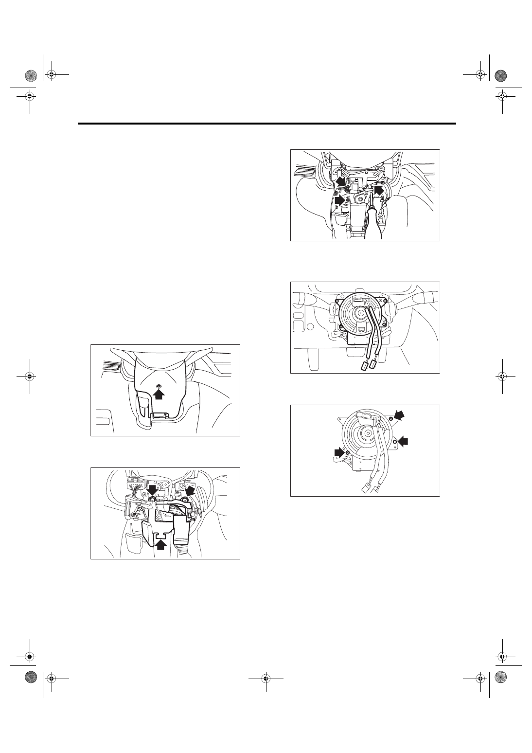
5) Remove the screws and remove the steering
column cover lower.
6) Remove the harness cover lock.
7) Remove the screws and detach the knee protec-
tor.
8) Remove the screws and remove the steering
column cover upper.
9) Disconnect the connector of roll connector and
steering angle sensor.
10) Remove the screws which secure the roll con-
nector to steering column.
11) Remove the vinyl tape binding the harness,
and remove the steering angle sensor from roll
connector.
WW-00547
LI-01143
LI-01144
AB-02604
VDC00885
VDC-23
Steering Angle Sensor
VEHICLE DYNAMICS CONTROL (VDC)
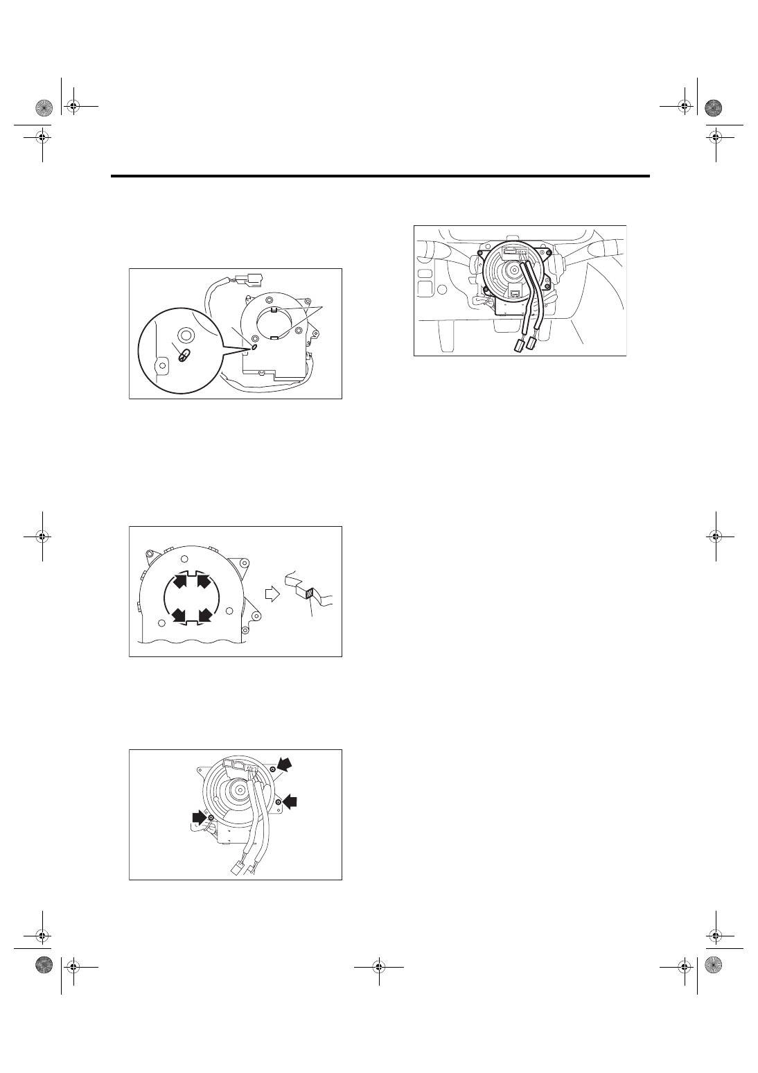
12) Turn the protrusion portion of new steering an-
gle sensor to match the alignment mark of inspec-
tion hole.
CAUTION:
Be careful not to allow foreign matter to enter
into inspection hole.
13) Align the center of roll connector. <Ref. to AB-
26, INSTALLATION, Roll Connector.>
14) Apply the grease provided with the new part on
the 4 locations of the protrusion on the steering an-
gle sensor.
15) Align the position of the protrusion and install
roll connector to steering angle sensor.
Tightening torque:
0.5 N·m (0.05 kgf-m, 0.36 ft-lb)
16) Install the roll connector to combination switch
and bind the harness with vinyl tape as originally
bound.
17) Install the steering wheel. <Ref. to PS-13, IN-
STALLATION, Steering Wheel.>
Tightening torque:
39 N·m (3.98 kgf-m, 28.8 ft-lb)
18) Install the airbag module to the steering wheel.
<Ref. to AB-15, INSTALLATION, Driver’s Airbag
Module.>
WARNING:
Always refer to “Airbag System” before per-
forming the service operation. <Ref. to AB-5,
CAUTION, General Description.>
19) Connect the ground cable to battery.
CAUTION:
After completion of installation, adjust the fol-
lowing two positions.
• Positioning to the center of steering angle
sensor
• Positioning the yaw rate & G sensors to zero
The above procedure is required for the VDC-
CM to identify vehicle position afterward. For
the setting procedures of the 2 steps above, re-
fer to “Adjustment” in “VDC Control Module &
Hydraulic Control Unit (VDCCM&H/U)”. <Ref. to
VDC-13, ADJUSTMENT, VDC Control Module
and Hydraulic Control Unit (VDCCM&H/U).>
(1) Protrusion portion
(2) Inspection hole
(3) Alignment mark
(1) Grease application location
VDC00209
(1)
(2)
(3)
ABS00435
(1)
VDC00885
AB-02604
VDC-24
Front ABS Wheel Speed Sensor
VEHICLE DYNAMICS CONTROL (VDC)
8. Front ABS Wheel Speed Sen-
sor
A: REMOVAL
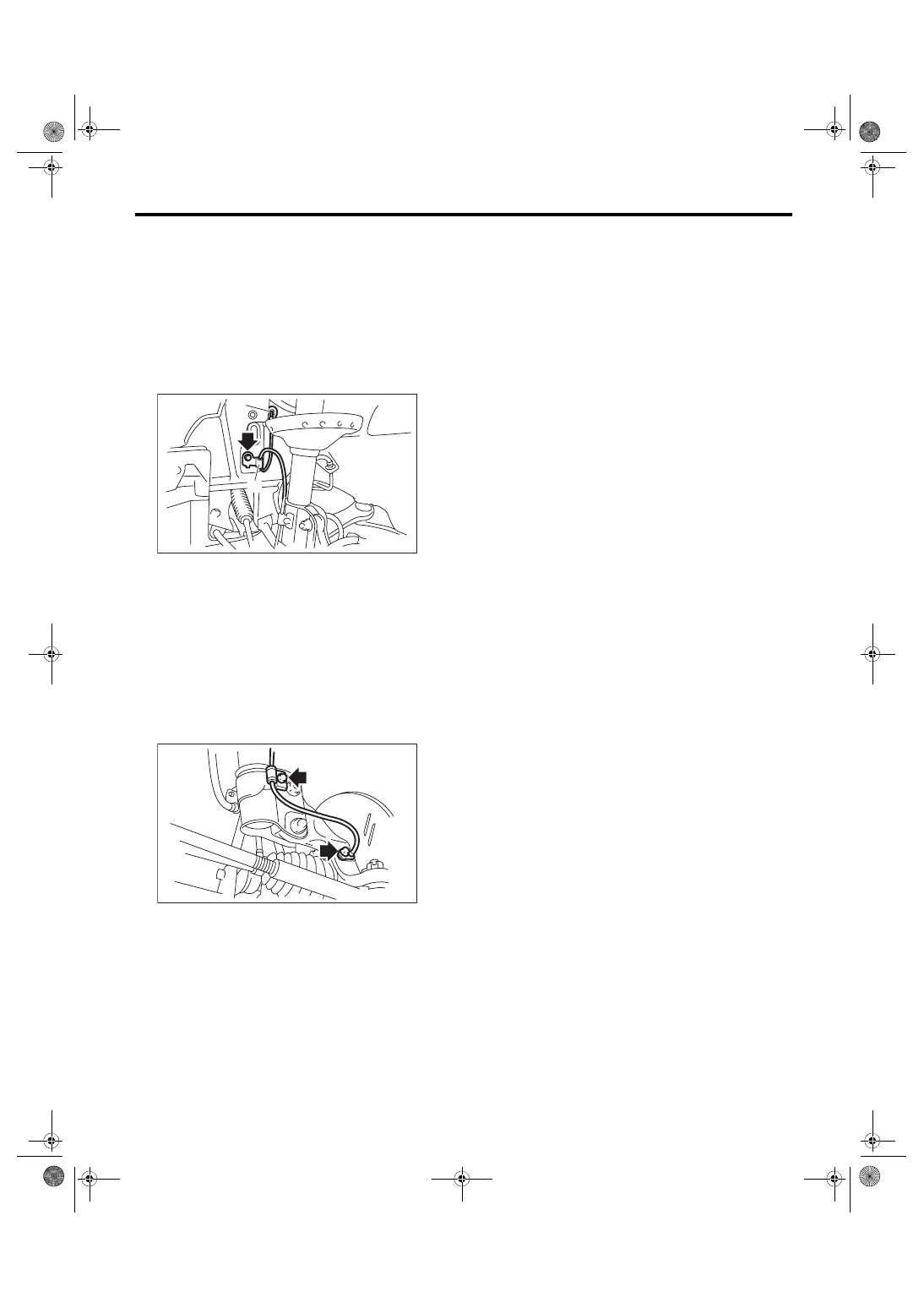
1) Disconnect the ground cable from battery.
2) Disconnect the ABS wheel speed sensor con-
nector located next to the front strut mounting
house in the engine compartment.
3) Remove the bolts and then remove the sensor
harness bracket.
4) Remove the bolts which secure the sensor har-
ness to the front strut.
5) Remove the bolts, and remove the front ABS
wheel speed sensor from the front housing.
CAUTION:
• Be careful not to damage the sensor.
• Do not apply excessive force to the sensor
harness.
B: INSTALLATION
CAUTION:
Be careful not to damage the sensor.
Install each part in the reverse order of removal.
Tightening torque:
Sensor:
7.5 N·m (0.76 kgf-m, 5.5 ft-lb)
Bracket:
33 N·m (3.36 kgf-m, 24.3 ft-lb)
NOTE:
• Check the identification (mark) on the harness to
make sure there is no warpage. (RH: K1 (White),
LH: K2 (Yellow))
• Check if the harness is not pulled and does not
come in contact with the suspension or body during
steering wheel effort.
C: INSPECTION
1. CHECK WITH SUBARU SELECT MONI-
TOR
1) Connect the Subaru Select Monitor to the data
link connector.
2) Select {Current Data Display & Save}. Check if
the speed indicated on the display changes in the
same manner as the speedometer reading during
acceleration/deceleration when the steering wheel
is in the straight-ahead position.
3) If the speed indicated on the display does not
change, check the ABS wheel speed sensor. <Ref.
to VDC-25, ABS WHEEL SPEED SENSOR, IN-
SPECTION, Front ABS Wheel Speed Sensor.>
(1) To the front ABS wheel speed sensor connector
(2) Sensor harness bracket
ABS00386
(1)
(2)
ABS00387
Нет комментариевНе стесняйтесь поделиться с нами вашим ценным мнением.
Текст