Subaru Impreza 3 / Impreza WRX / Impreza WRX STI. Service manual — part 522
VDC-17
VDC Sequence Control
VEHICLE DYNAMICS CONTROL (VDC)
5. VDC Sequence Control
A: OPERATION
1) While the VDC sequence control is performed, the operation of the hydraulic unit can be checked using
the brake tester or pressure gauge after the hydraulic unit solenoid valve is operated.
2) VDC sequence control can be started by Subaru Select Monitor.
1. VDC SEQUENCE CONTROL WITH SUBARU SELECT MONITOR
NOTE:
In the event of any trouble, sequence control will not operate.
1) Connect the Subaru Select Monitor to data link connector under the driver’s side instrument panel lower
cover.
2) Turn the ignition switch to ON.
3) Run the “PC application for Subaru Select Monitor”.
4) Set the Subaru Select Monitor to “Brake Control System” mode.
5) When the “VDC Inspection Mode” is selected from the “Function Check Sequence” menu, the “VDC se-
quence control” will start.
6) Press the “OK” after “Press “OK”” is displayed.
7) Operation points will be displayed on Subaru Select Monitor.
VDC-18
VDC Sequence Control
VEHICLE DYNAMICS CONTROL (VDC)
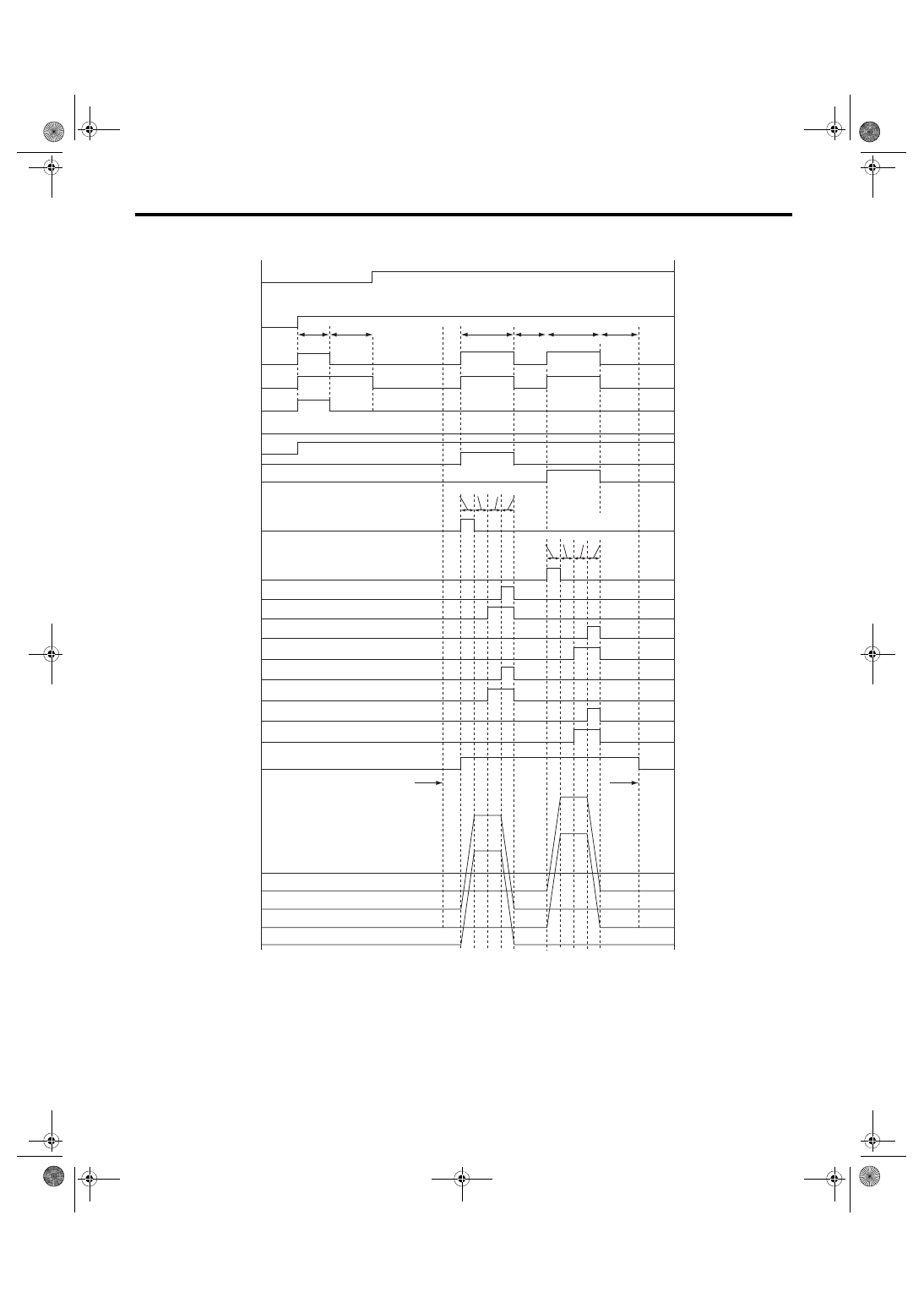
2. CONDITIONS FOR VDC SEQUENCE CONTROL
(20) ON
ON
(23)
(23)
(23)
(4)
(37)
(5)
(19)
(32)
(3)
(2)
(1)
(22)
(22)
(23)
(22)
(22)
(22)
(22)
V max < 4 km/h (2.5 MPH)
V max < 10 km/h (6 MPH)
OFF
OFF
OFF
OFF
OFF
ON
VDC
(21)
(27)
(28)
(25)
(26)
(24)
(29)
(30) (31)
(25)
(24)
(8)
(7)
(9)
(10)
OFF
(11)
OFF
(12)
OFF
(14)
OFF
(15)
OFF
(16)
OFF
(13)
OFF
(18)
OFF
(17)
(6)
(33)
(35)
(34)
(36)
VDC00607
(29)
(30) (31)
(25)
VDC-19
VDC Sequence Control
VEHICLE DYNAMICS CONTROL (VDC)
NOTE:
The control operation starts at point A.
B: SPECIFICATION
1. CONDITIONS FOR COMPLETION OF
VDC SEQUENCE CONTROL
When the following conditions develop, the VDC sequence control stops and VDC operation is returned to
the normal control mode.
• When the speed of at least one wheel reaches 10 km/h (6 MPH).
• When the brake pedal is pressed during sequence control and the stop light switch is set to ON.
• After completion of VDC sequence control.
• When a malfunction is detected.
(1)
All wheel speed
(14) FR compression valve
(26) 1.6 seconds
(2)
Ignition key
(15) RR decompression valve
(27) Point A
(3)
ABS warning light
(16) RR compression valve
(28) Reset
(4)
VDC warning light
(17) RL decompression valve
(29) 0.8 seconds
(5)
Stop light switch
(18) RL compression valve
(30) 1.2 seconds
(6)
Valve relay
(19) Pump motor
(31) 0.4 seconds
(7)
VDC switching valve 1 FL
(20) 1.5 seconds
(32) Master cylinder pressure
(8)
VDC switching valve 1 FR
(21) Approx. 3 seconds
(33) FR wheel cylinder pressure
(9)
VDC switching valve 2 FL
(22) Light OFF
(34) FL wheel cylinder pressure
(10) VDC switching valve 2 FR
(23) Light ON
(35) RL wheel cylinder pressure
(11) FL decompression valve
(24) 3.4 seconds
(36) RR wheel cylinder pressure
(12) FL compression valve
(25) 1 second
(37) Hill start assist warning light
(13) FR decompression valve
VDC-20
Yaw Rate and G Sensor
VEHICLE DYNAMICS CONTROL (VDC)
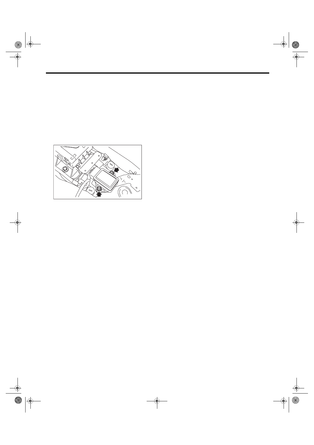
6. Yaw Rate and G Sensor
A: REMOVAL
1) Disconnect the ground cable from battery.
2) Remove the console box. <Ref. to EI-51, Con-
3) Disconnect the connector from yaw rate & G
sensor.
4) Remove the nut and remove the yaw rate & G
sensor.
CAUTION:
Do not drop or hit the yaw rate & G sensor.
B: INSTALLATION
Install each part in the reverse order of removal.
Tightening torque:
7.5 N·m (0.76 kgf-m, 5.5 ft-lb)
CAUTION:
After completion of installation, set the follow-
ing two positions.
• Positioning to the center of steering angle
sensor
• Positioning the yaw rate & G sensors to zero
The above procedure is required VDCCM&H/U
to identify the vehicle position afterward. For
the setting procedures of the 2 steps above, re-
fer to “VDC Control Module and Hydraulic Con-
trol Unit (VDCCM&H/U)”. <Ref. to VDC-13,
ADJUSTMENT, VDC Control Module and Hy-
draulic Control Unit (VDCCM&H/U).>
VDC00453
Нет комментариевНе стесняйтесь поделиться с нами вашим ценным мнением.
Текст