Subaru Impreza 3 / Impreza WRX / Impreza WRX STI. Service manual — part 521
VDC-13
VDC Control Module and Hydraulic Control Unit (VDCCM&H/U)
VEHICLE DYNAMICS CONTROL (VDC)
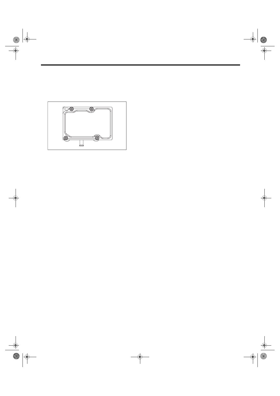
9) Using a TORX
®
bit E5, attach/tighten new
screws in the order of (1) through (4).
CAUTION:
Always use new screws.
Tightening torque:
1.5 N·m (0.15 kgf-m, 1.1 ft-lb)
10) Check that there is no foreign matter in mating
surface between the VDCCM&H/U.
11) Using a TORX
®
bit E5, tighten the screws in the
order of (1) through (4) again.
Tightening torque:
3 N·m (0.31 kgf-m, 2.2 ft-lb)
12) Check that there is no gap in the mating sur-
face between VDCCM&H/U.
13) Install the VDCCM&H/U to the vehicle.
14) Bleed air from the brake system. <Ref. to BR-
15) Perform the selection · registration operation of
parameter. <Ref. to VDC(diag)-21, PARAMETER
SELECTION, OPERATION, Subaru Select Moni-
tor.>
NOTE:
• After replacing the VDCCM, be sure to perform
the selection · registration operation of parameter.
• For the selection and registration of parameter,
the Subaru Select Monitor is required.
• When the registration has not been performed,
the DTC code “Parameter selection error” is detect-
ed together with the ABS/EBD/VDC warning light il-
lumination.
16) Check the parameter to confirm that the ap-
plied models and grades of the relevant vehicle are
included. <Ref. to VDC(diag)-21, PARAMETER
CHECK, OPERATION, Subaru Select Monitor.>
17) If the applied models and grades of the relevant
vehicle are not included, perform the selection ·
registration operation of parameter with the {Con-
firm on parameter} screen again. <Ref. to VDC(di-
ag)-21, PARAMETER SELECTION, OPERATION,
18) Execute Clear Memory after parameter selec-
tion and registration operations because the DTC
for “Parameter selection error” is memorized.
E: ADJUSTMENT
When the following replacement, removal and in-
stallation are performed, be sure to perform the
centering of the steering angle sensor and zero
point setting of yaw rate & G sensor.
• VDCCM&H/U
• Steering angle sensor
• Yaw rate & G sensor
• Steering wheel parts (Including airbag)
• Suspension parts
• Wheel alignment adjustment
1) Park the vehicle straight on a level surface. (With
engine operating in the “Neutral” range)
2) Check that steering wheel is positioned at the
center. (When the center position is not correct, ad-
just the wheel alignment.)
3) Set the Subaru Select Monitor to the vehicle,
and select the {Set mode Str.A.Sen.N&Lat.GS-
en.0p} in the «Function Check Sequence» screen.
(Follow the steps on the display.)
4) On «Brake Control System» display, select {Cur-
rent Data Display & Save}, and check that the
steering angle sensor shows “0 deg”.
5) When the “0 deg” is not displayed, repeat the
above steps and check that the “0 deg” is dis-
played.
6) Drive the vehicle for 10 minutes, and check that
the ABS and VDC warning light is not illuminated.
7) Check that there is no unnecessary VDC opera-
tion or steering control loss. If there is a malfunc-
tion, repeat the steps above.
ABS00432
(4)
(2)
(1)
(3)
VDC-14
ABS Sequence Control
VEHICLE DYNAMICS CONTROL (VDC)
4. ABS Sequence Control
A: OPERATION
1) While the ABS sequence control is being performed, the operation of the hydraulic unit can be checked us-
ing the brake tester or pressure gauge after the hydraulic unit solenoid valve operation.
2) ABS sequence control can be started by the Subaru Select Monitor.
1. ABS SEQUENCE CONTROL WITH SUBARU SELECT MONITOR
NOTE:
In the event of any trouble, the ABS sequence control will not operate.
1) Connect the Subaru Select Monitor to data link connector under the driver’s side instrument panel lower
cover.
2) Turn the ignition switch to ON.
3) Run the “PC application for Subaru Select Monitor”.
4) Set the Subaru Select Monitor to “Brake Control System” mode.
5) When the “Function Check Sequence” is selected, the “ABS sequence control” will start.
6) Execute the following operations when the message “Press Brake Pedal Firmly” is displayed.
(1) When using a brake tester, press the brake pedal pad with a force of 1,000 N (102 kgf, 225 lbf).
(2) When using a pressure gauge, press the brake pedal so that the pressure gauge indicates 3,500 kPa
(36 kgf/cm
2
, 511 psi).
7) Press the “OK” after “Press “OK”” is displayed.
8) The brake system being operated is displayed on the Subaru Select Monitor.
VDC-15
ABS Sequence Control
VEHICLE DYNAMICS CONTROL (VDC)
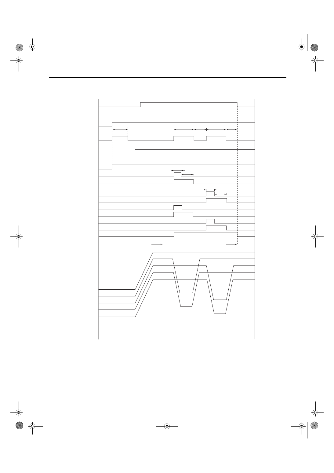
2. CONDITIONS FOR ABS SEQUENCE CONTROL
ABS00943
(1)
(2)
(3)
(4)
(5)
(6)
(7)
(8)
(9)
(10)
(11)
(12)
(13)
(14)
(24)
(25)
(28)
(27)
(26)
V max < 4 km/h (2.5 MPH)
OFF
(16)
(17)
OFF
ON
OFF
ON
OFF
ON
(21)
(18)
OFF
ON
OFF
ON
OFF
ON
OFF
ON
OFF
ON
OFF
ON
OFF
ON
OFF
ON
ON
(15)
(19)
(18)
(19)
V max < 10 km/h (6 MPH)
(16)
(17)
(17)
(16)
(16)
(21)
(18)
(22)
(23)
(20)
VDC-16
ABS Sequence Control
VEHICLE DYNAMICS CONTROL (VDC)
NOTE:
The control operation starts at point A.
B: SPECIFICATION
1. CONDITIONS FOR COMPLETION OF ABS SEQUENCE CONTROL
When the following conditions develop, the ABS sequence control stops and ABS operation is returned to the
normal control mode.
• When the speed of at least one wheel reaches 10 km/h (6 MPH).
• When the brake pedal is released during ABS sequence control and the stop light switch is becomes OFF.
• After completion of ABS sequence control.
• When a malfunction is detected.
(1)
All wheel speed
(11) RR compression valve
(20) 0.6 sec.
(2)
Ignition key
(12) RL decompression valve
(21) 0.4 sec.
(3)
ABS warning light
(13) RL compression valve
(22) Point A
(4)
Stop light switch
(14) Pump motor
(23) Reset
(5)
Valve relay
(15) 1.5 sec.
(24) Master cylinder pressure
(6)
FL decompression valve
(16) Light OFF
(25) FL wheel cylinder pressure
(7)
FL compression valve
(17) Light ON
(26) FR wheel cylinder pressure
(8)
FR decompression valve
(18) 1.0 sec.
(27) RR wheel cylinder pressure
(9)
FR compression valve
(19) 1.4 sec.
(28) RL wheel cylinder pressure
(10) RR decompression valve
Нет комментариевНе стесняйтесь поделиться с нами вашим ценным мнением.
Текст