Subaru Impreza 3 / Impreza WRX / Impreza WRX STI. Service manual — part 524
VDC-25
Front ABS Wheel Speed Sensor
VEHICLE DYNAMICS CONTROL (VDC)
2. ABS WHEEL SPEED SENSOR
1) Check the tip of the ABS wheel speed sensor for
foreign particles or damage. If necessary, clean the
tip or replace the ABS wheel speed sensor.
2) Check the ABS wheel speed sensor cable for
discontinuity. If defective, replace the ABS wheel
speed sensor.
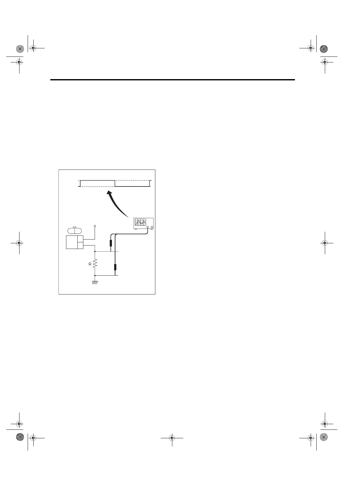
3) Connect a 12 V power supply to No. 2 terminal of
sensor connector as shown in the figure, then at-
tach resistance to the No. 1 terminal. Rotate the
wheel at about 2.75 km/h (2 MPH), and measure
the voltage using an oscilloscope.
Standard value of output voltage:
0.7 — 1.4 V
4) Replace the ABS wheel speed sensor if the in-
spection result is not within the standard value.
(1) Oscilloscope
(2) ABS wheel speed sensor
ABS00388
(2)
(1)
100
1.4 V
0.7 V
12 V
2
1
1
2
VDC-26
Rear ABS Wheel Speed Sensor
VEHICLE DYNAMICS CONTROL (VDC)
9. Rear ABS Wheel Speed Sen-
sor
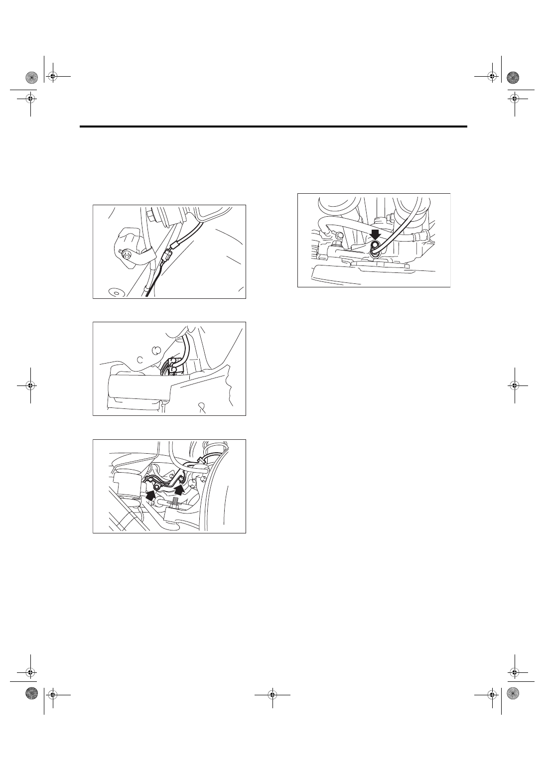
A: REMOVAL
1) Disconnect the ground cable from battery.
2) Disconnect the connector from the rear ABS
wheel speed sensor.
3) Remove the sensor harness clamp of the rear
sub frame.
4) Remove the bolts and then remove the sensor
harness bracket from the upper arm.
5) Remove the bolts, and remove the rear ABS
wheel speed sensor from the rear axle.
CAUTION:
• Be careful not to damage the sensor.
• Do not apply excessive force to the sensor
harness.
B: INSTALLATION
CAUTION:
Be careful not to damage the sensor.
Install each part in the reverse order of removal.
Tightening torque:
Sensor:
7.5 N·m (0.76 kgf-m, 5.5 ft-lb)
Bracket:
7.5 N·m (0.76 kgf-m, 5.5 ft-lb)
NOTE:
Check the identification (mark) on the harness to
make sure there is no warpage. (RH: P5 (White),
LH: P6 (Yellow))
C: INSPECTION
1. ABS WHEEL SPEED SENSOR
Refer to “INSPECTION” in “Front ABS Wheel
Speed Sensor”. <Ref. to VDC-24, INSPECTION,
Front ABS Wheel Speed Sensor.>
RS-00266
ABS-01015
RS-00257
FU-03357
VDC-27
Front Magnetic Encoder
VEHICLE DYNAMICS CONTROL (VDC)
10.Front Magnetic Encoder
A: REMOVAL
Refer to “Front Hub Bearing” for removal, because
the front magnetic encoder is integrated with front
hub bearing. <Ref. to DS-18, REMOVAL, Front
B: INSTALLATION
Refer to “Front Hub Bearing” for installation, be-
cause the front magnetic encoder is integrated with
front hub bearing. <Ref. to DS-19, INSTALLATION,
C: INSPECTION
Visually check the magnetic encoder for any dam-
age. If necessary, replace with a new hub unit bear-
ing.
NOTE:
Because the magnetic encoder is integrated with
hub unit bearing assembly, replace the hub unit
bearing with a new part if there is any defect found
on the magnetic encoder.
VDC-28
Rear Magnetic Encoder
VEHICLE DYNAMICS CONTROL (VDC)
11.Rear Magnetic Encoder
A: REMOVAL
Refer to “Rear Hub Unit Bearing” for removal, be-
cause the rear magnetic encoder is integrated with
rear hub unit bearing. <Ref. to DS-24, REMOVAL,
B: INSTALLATION
Refer to “Rear Hub Unit Bearing” for installation,
because the rear magnetic encoder is integrated
with rear hub unit bearing. <Ref. to DS-25, INSTAL-
LATION, Rear Hub Unit Bearing.>
C: INSPECTION
Visually check the magnetic encoder parts for any
damage. If necessary, replace with a new hub unit
bearing.
NOTE:
Because the magnetic encoder is integrated with
hub unit bearing assembly, replace the hub unit
bearing with a new part if there is any defect found
on the magnetic encoder.
Нет комментариевНе стесняйтесь поделиться с нами вашим ценным мнением.
Текст