Subaru Impreza 3 / Impreza WRX / Impreza WRX STI. Service manual — part 438
6MT-89
Reverse Idler Gear Assembly
MANUAL TRANSMISSION AND DIFFERENTIAL
19.Reverse Idler Gear Assembly
A: REMOVAL
1) Remove the manual transmission assembly
from the vehicle. <Ref. to 6MT-31, REMOVAL,
Manual Transmission Assembly.>
2) Prepare the transmission for overhaul. <Ref. to
6MT-37, Preparation for Overhaul.>
3) Remove the neutral position switch, back-up
light switch and harness. <Ref. to 6MT-41, RE-
MOVAL, Neutral Position Switch.> <Ref. to 6MT-
39, REMOVAL, Back-up Light Switch.>
4) Remove the extension case. <Ref. to 6MT-43,
5) Remove the transfer driven gear. <Ref. to 6MT-
55, REMOVAL, Transfer Driven Gear.>
6) Remove the center differential. <Ref. to 6MT-57,
REMOVAL, Center Differential.>
7) Remove the transmission case. <Ref. to 6MT-
58, REMOVAL, Transmission Case.>
8) Remove the reverse idler gear assembly. <Ref.
to 6MT-65, REMOVAL, Main Shaft Assembly.>
B: INSTALLATION
1) Select the reverse fork rod. <Ref. to 6MT-112,
ADJUSTMENT, Shifter Fork and Rod.>
2) Install the reverse idler gear assembly. <Ref. to
6MT-66, INSTALLATION, Main Shaft Assembly.>
3) Install the transmission case. <Ref. to 6MT-60,
INSTALLATION, Transmission Case.>
4) Install the center differential. <Ref. to 6MT-57,
INSTALLATION, Center Differential.>
5) Install the transfer driven gear. <Ref. to 6MT-55,
INSTALLATION, Transfer Driven Gear.>
6) Install the extension case. <Ref. to 6MT-43, IN-
7) Install the neutral position switch, back-up light
switch and harness. <Ref. to 6MT-41, INSTALLA-
TION, Neutral Position Switch.> <Ref. to 6MT-39,
INSTALLATION, Back-up Light Switch.>
8) Install the manual transmission assembly to the
vehicle. <Ref. to 6MT-33, INSTALLATION, Manual
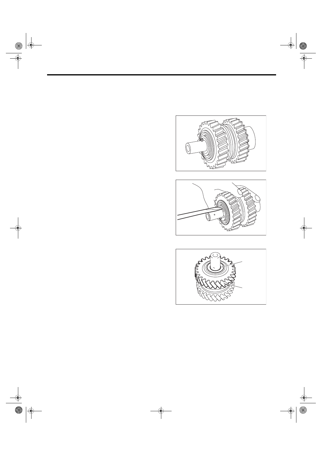
C: DISASSEMBLY
NOTE:
Sleeves and reverse gears meet at a specified po-
sition. Before disassembly, mark the meeting posi-
tion of the sleeve and hub.
1) Remove the straight pin.
2) Remove the snap ring and washer.
3) Remove the counter high & low washer and re-
verse idler gear.
(A) Counter high and low washer
(B) Reverse idler gear
MT-00617
MT-00618
MT-00619
(B)
(A)
6MT-90
Reverse Idler Gear Assembly
MANUAL TRANSMISSION AND DIFFERENTIAL
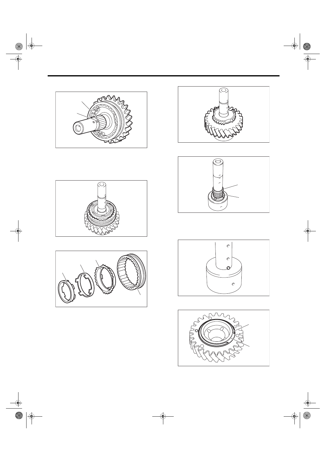
4) Remove the knock pin and reverse idler gear
needle bearing.
5) Remove the collar.
6) Remove the reverse sleeve.
7) Remove the outer baulk ring, reverse synchro
cone and inner baulk ring from the reverse sleeve.
8) Remove reverse idler gear No. 2.
9) Remove the counter high & low washer and nee-
dle bearing.
10) Remove the knock pin.
11) Remove the snap ring and friction plate from
reverse gear.
(A) Knock pin
(B) Reverse idler gear needle bearing
(A) Reverse sleeve
(B) Outer baulk ring
(C) Reverse synchro cone
(D) Inner baulk ring
MT-00620
(A)
(B)
MT-00622
MT-01507
(A)
(B)
(C)
(D)
(A) Needle bearing
(B) Counter high and low washer
(A) Snap ring
(B) Friction plate
MT-00624
MT-00625
(A)
(B)
MT-00626
MT-00627
(B)
(A)
6MT-91
Reverse Idler Gear Assembly
MANUAL TRANSMISSION AND DIFFERENTIAL
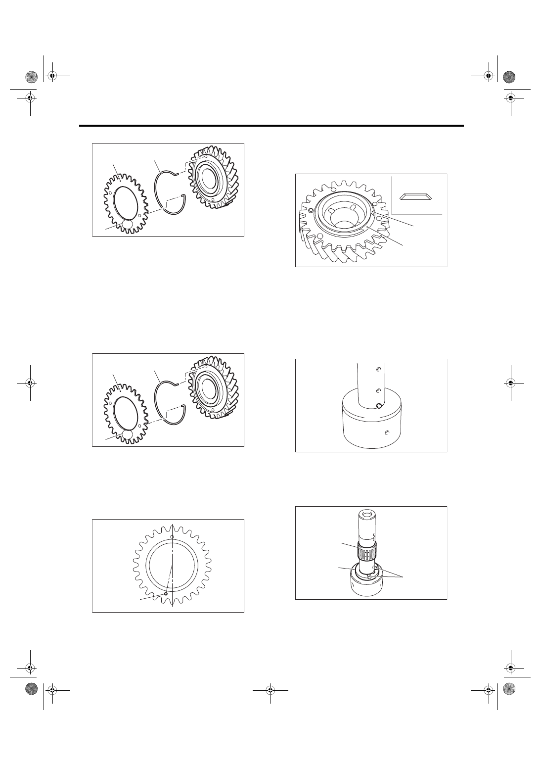
12) Remove the sub gear and spring.
D: ASSEMBLY
1) Attach the sub gear and spring.
NOTE:
• Turn the white marking on the hook section to-
wards the sub gear side, and attach the spring.
• Point the stamp (marking A) towards the outside,
and install the sub gear.
• While paying attention to the direction of the sub
gear attachment hole, attach the spring and sub
gear.
2) Install the friction plate and snap ring.
NOTE:
Confirm that the friction plate is installed in the
proper direction.
3) Apply adequate transmission gear oil to the
shaft, needle bearing and reverse drive gear inner
surface.
4) Install the knock pin.
5) Install the counter high & low washer and needle
bearing.
NOTE:
Point the groove towards the reverse idler gear,
and attach the washer.
(A) Sub gear
(B) Spring
(C) Stamp (marking A)
(A) Sub gear
(B) Spring
(C) Stamp (marking A)
(A) Attachment hole
MT-00628
(B)
(A)
(C)
A
MT-00628
(B)
(A)
(C)
A
MT-00629
(A)
A
(A) Friction plate
(B) Snap ring
(C) Snap ring side
(D) Sub gear side
(A) Groove
(B) Counter high and low washer
(C) Needle bearing
MT-00630
(C)
(D)
(A)
(B)
MT-00626
MT-00631
(C)
(B)
(A)
6MT-92
Reverse Idler Gear Assembly
MANUAL TRANSMISSION AND DIFFERENTIAL
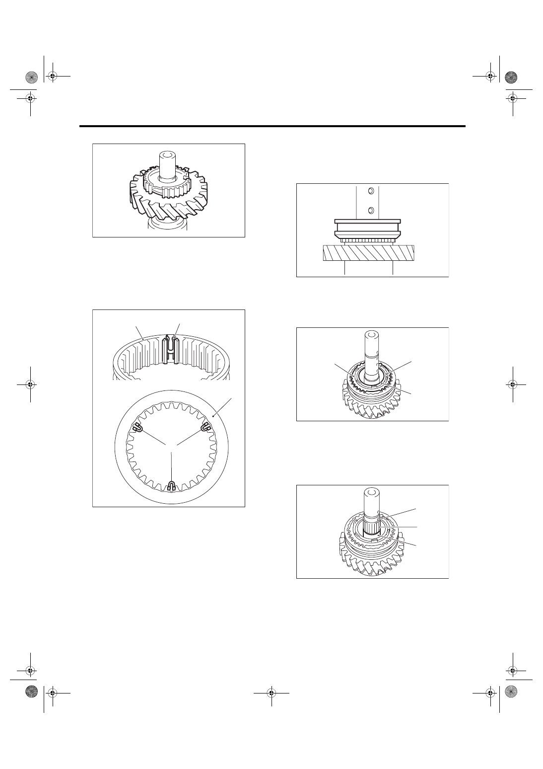
6) Install the reverse idler gear No. 2.
7) Attach the shifting insert key to the appropriate
location of the reverse sleeve.
NOTE:
• The location angle of each shifting insert key is
120°.
• Refer to the following figure to install the shifting
insert key.
8) Attach the reverse sleeve to the reverse idler
gear No. 2.
NOTE:
Confirm that the reverse sleeve is installed in the
proper direction.
9) Apply adequate transmission gear oil to the col-
lar, needle bearing and reverse drive gear inner
surface.
10) Install the outer baulk ring, reverse synchro
cone and inner baulk ring.
11) Install the collar and needle bearing, then the
knock pin.
(A) Reverse sleeve
(B) Shifting insert key
MT-00632
(B)
(A)
(B)
(A)
MT-00633
(A) Outer baulk ring
(B) Reverse synchro cone
(C) Inner baulk ring
(A) Collar
(B) Needle bearing
(C) Knock pin
MT-00634
MT-00635
(A)
(B)
(C)
MT-00636
(C)
(B)
(A)
Нет комментариевНе стесняйтесь поделиться с нами вашим ценным мнением.
Текст