Subaru Impreza 3 / Impreza WRX / Impreza WRX STI. Service manual — part 439
6MT-93
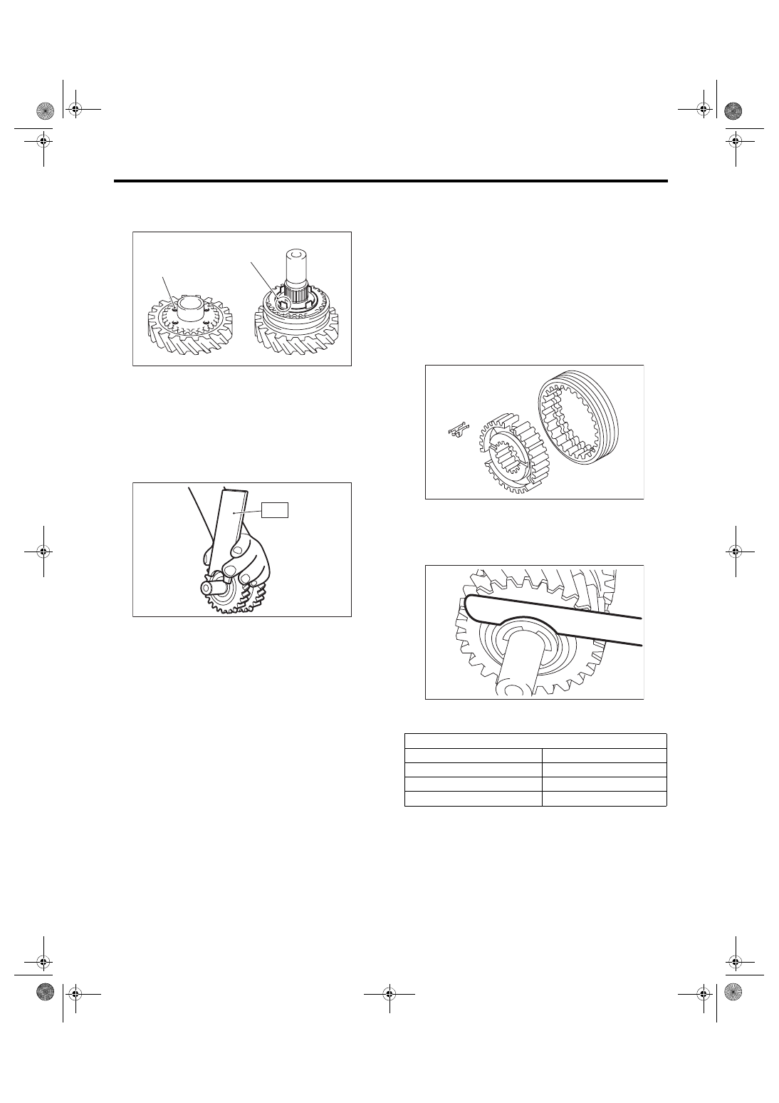
Reverse Idler Gear Assembly
MANUAL TRANSMISSION AND DIFFERENTIAL
12) Match the protrusion of the reverse synchro
cone to the hole on the reverse idler gear, and in-
stall the reverse idler gear.
13) Point the groove towards the reverse idler gear,
and attach the counter high & low washer and the
washer.
14) Using the ST, install the snap ring.
ST 18672AA000 GUIDE CLIP
15) Inspect and adjust the clearance between the
snap ring and the washer. <Ref. to 6MT-93, IN-
SPECTION, Reverse Idler Gear Assembly.>
16) Install a new straight pin.
E: INSPECTION
Disassembled parts should be washed with clean-
ing solvent first, then inspected carefully.
1) Bearing
Replace the bearings in the following cases.
• Wear, rusting or damage of the bearings
• The bearing does not rotate smoothly or an ab-
normal noise is emitted when turning.
• The bearing has other defects.
2) Bushing (each gear)
Replace the bushing in following cases.
• The sliding surface is damaged or abnormally
worn.
3) Gear
Replace gears in the following cases.
• The gear teeth surface is damaged or excessive-
ly worn.
• The contact area of the baulk ring is damaged.
• The inner face of the gear is worn.
4) Baulk ring, synchro cone
Replace the baulk ring and synchro cone in the fol-
lowing cases.
• Wear, rusting or damage of the baulk ring
5) Shifting insert key
Replace the shifting insert key if deformed, exces-
sively worn or defective in any way.
6) Check clearance between the snap ring and
washer.
Clearance specification:
0.1 — 0.3 mm (0.0039 — 0.0118 in)
If the clearance is out of the specification, select a
snap ring from the following table and replace it.
After replacing the snap ring, inspect the clearance.
(A) Protrusion on the reverse synchro cone
(B) Hole of the reverse idler gear
MT-01508
(A)
(B)
MT-00638
ST
Snap ring
Part No.
Thickness mm (in)
031319000
1.50 (0.059)
805019030
1.60 (0.062)
805019010
1.72 (0.068)
MT-00581
MT-00639
6MT-94
Drive Pinion Shaft Assembly
MANUAL TRANSMISSION AND DIFFERENTIAL
20.Drive Pinion Shaft Assembly
A: REMOVAL
1) Remove the manual transmission assembly
from the vehicle. <Ref. to 6MT-31, REMOVAL,
Manual Transmission Assembly.>
2) Prepare the transmission for overhaul. <Ref. to
6MT-37, Preparation for Overhaul.>
3) Remove the neutral position switch, back-up
light switch and harness. <Ref. to 6MT-41, RE-
MOVAL, Neutral Position Switch.> <Ref. to 6MT-
39, REMOVAL, Back-up Light Switch.>
4) Remove the extension case. <Ref. to 6MT-43,
5) Remove the transfer driven gear. <Ref. to 6MT-
55, REMOVAL, Transfer Driven Gear.>
6) Remove the center differential. <Ref. to 6MT-57,
REMOVAL, Center Differential.>
7) Remove the transmission case. <Ref. to 6MT-
58, REMOVAL, Transmission Case.>
8) Remove the individual gear assemblies. <Ref. to
6MT-65, REMOVAL, Main Shaft Assembly.>
9) Remove the drive pinion shaft assembly.
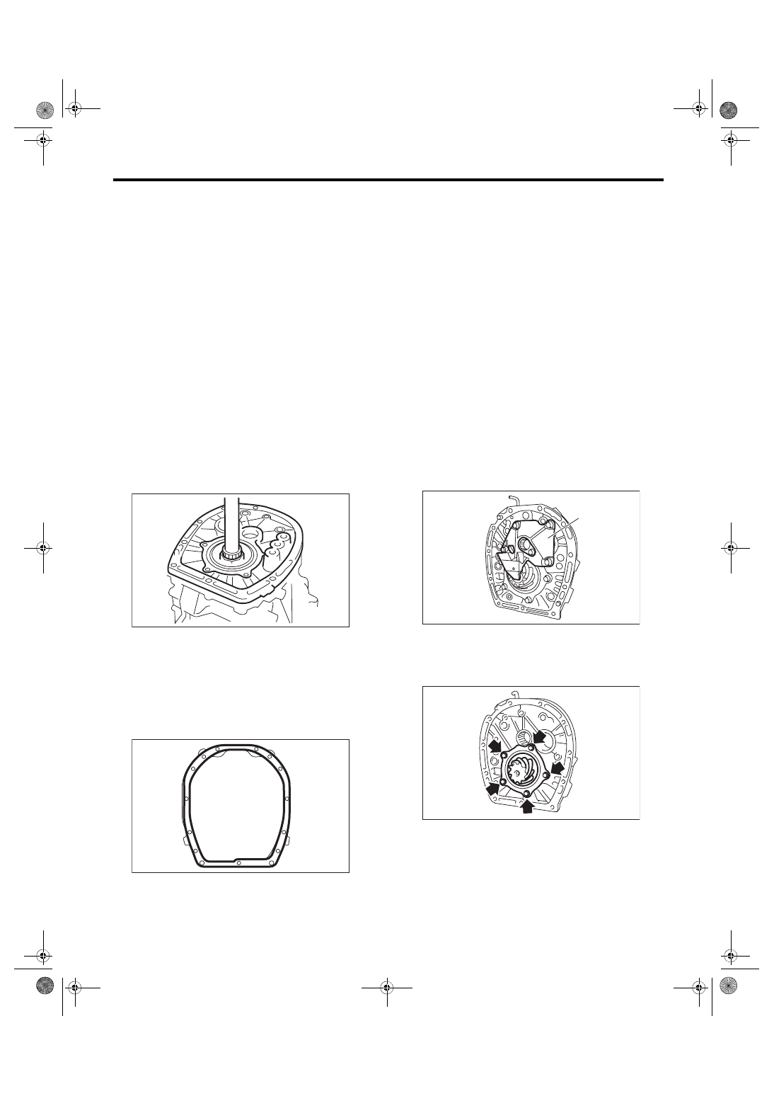
B: INSTALLATION
1) Remove any remaining gasket material from the
drive plate and clutch housing.
2) Apply liquid gasket to the clutch housing.
Liquid gasket:
THREE BOND 1215 (Part No. 004403007) or
equivalent
3) Install the individual gear assemblies. <Ref. to
6MT-66, INSTALLATION, Main Shaft Assembly.>
4) Install the transmission case. <Ref. to 6MT-60,
INSTALLATION, Transmission Case.>
5) Install the center differential. <Ref. to 6MT-57,
INSTALLATION, Center Differential.>
6) Install the transfer driven gear. <Ref. to 6MT-55,
INSTALLATION, Transfer Driven Gear.>
7) Install the extension case. <Ref. to 6MT-43, IN-
8) Install the neutral position switch, back-up light
switch and harness. <Ref. to 6MT-41, INSTALLA-
TION, Neutral Position Switch.> <Ref. to 6MT-39,
INSTALLATION, Back-up Light Switch.>
9) Install the manual transmission assembly to the
vehicle. <Ref. to 6MT-33, INSTALLATION, Manual
C: DISASSEMBLY
NOTE:
Replace the drive pinion shaft and hypoid driven
gear as a set.
1) Remove the oil guide A.
2) Remove the drive pinion shaft and shim from the
adapter plate.
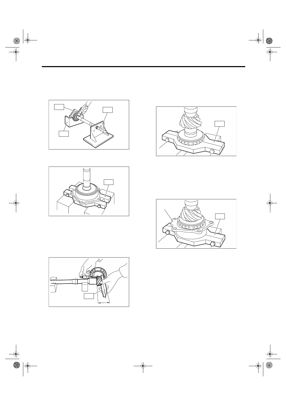
3) Affix the ST to the work table.
ST 18664AA000 BASE
4) Flatten the tab of the lock nut.
MT-00640
MT-00532
(A) Oil guide A
MT-01624
(A)
MT-00642
6MT-95
Drive Pinion Shaft Assembly
MANUAL TRANSMISSION AND DIFFERENTIAL
5) Attach ST3 to the lock nut, and set the drive pin-
ion shaft to ST. Remove the lock nut and lock
washer.
ST1 18667AA000
HOLDER
ST2 18664AA000
BASE
ST3 18621AA000
ADAPTER WRENCH
6) Using the ST, remove the double taper roller
bearing assembly.
ST 18723AA000 REMOVER
D: ASSEMBLY
1) Using the ST, measure drive pinion measure-
ment A.
NOTE:
When selecting the drive pinion shim, refer to mea-
surement A.
ST 398643600
GAUGE
2) Using the ST and a press, attach the inner bear-
ing of the double taper roller bearing to the drive
pinion shaft.
ST 18723AA000 REMOVER
CAUTION:
Do not apply pressure in excess of 40 kN (4.0
ton, 4.4 US ton, 3.9 Imp ton).
3) Using the ST and a press, attach the outer race
and the double taper roller bearing to the drive pin-
ion shaft.
ST 18723AA000 REMOVER
NOTE:
• Use a new double taper roller bearing.
• Push in to a position where the bearing rotates
smoothly.
MT-00643
ST2
ST3
ST1
ST
MT-00644
MT-00645
A
ST
(A) Outer race
MT-00646
ST
MT-00647
(A)
ST
6MT-96
Drive Pinion Shaft Assembly
MANUAL TRANSMISSION AND DIFFERENTIAL
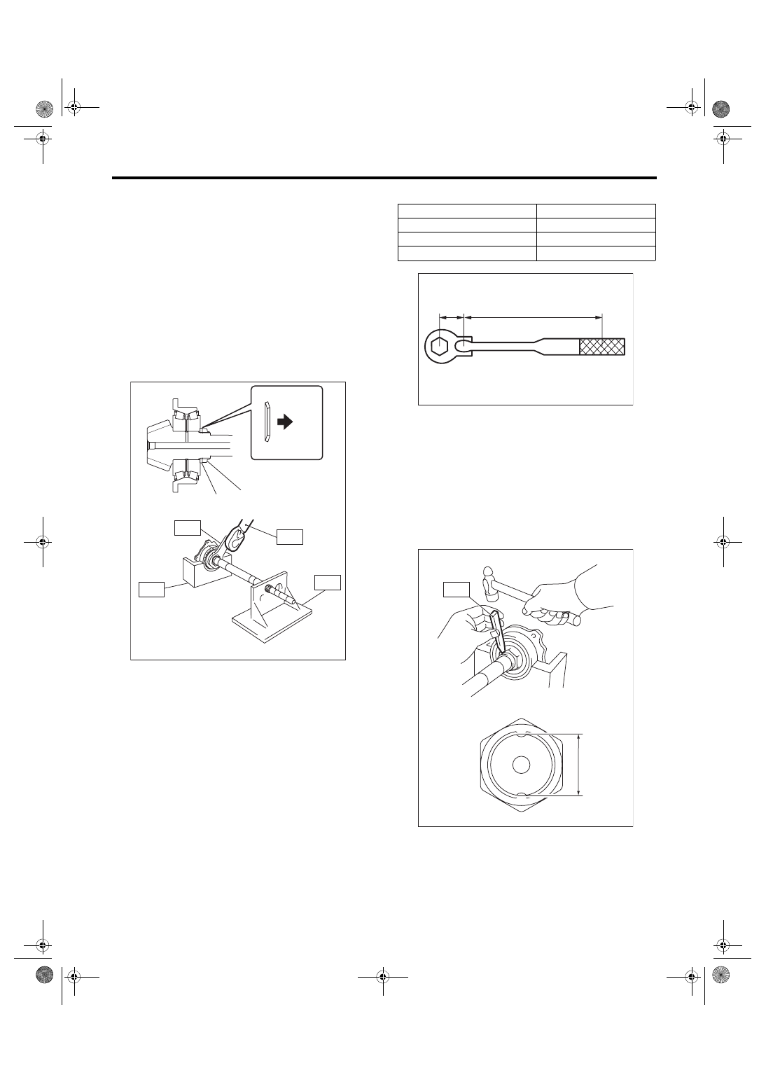
4) Attach a new lock washer and a new lock nut.
5) Set the ST to the drive pinion, and tighten the
lock nut.
ST1 18667AA000
HOLDER
ST2 18664AA000
BASE
ST3 18621AA000
ADAPTER WRENCH
ST4 18852AA000
TORQUE WRENCH
NOTE:
• Tighten using the ST and the straight line torque
wrench.
• Make sure the lock washer is installed in the
proper direction.
Tightening torque:
265 N·m (27.0 kgf-m, 195.4 ft-lb)
NOTE:
When using a torque wrench other than ST4, use
the calculation below to calculate and tighten the
lock nut.
Tighten using the ST and the straight line torque
wrench.
T = L1/(0.1 + L1) × 285
6) Measure the starting torque. <Ref. to 6MT-97,
INSPECTION, Drive Pinion Shaft Assembly.>
7) Using the ST, crimp the lock nut in 2 locations,
with dimensions within A 37±0.5 mm (1.46±0.02
in).
ST 18670AA000 PUNCH
NOTE:
Do not damage the crimp area of the lock nut.
(A) Lock washer
(B) Lock nut
(C) Nut side
MT-02715
(B)
(A)
(C)
ST2
ST4
ST3
ST1
T
N·m (kgf-m, ft-lb) Torque wrench setting
L1
m (in) Torque wrench length
0.1 m (3.94 in)
Length of ST
285 N·m (29.0 kgf-m, 210 ft-lb) Tightening torque (lock nut)
(A) 0.1 m (3.94 in)
MT-00614
(A)
L1
MT-00649
A
ST
Нет комментариевНе стесняйтесь поделиться с нами вашим ценным мнением.
Текст