Subaru Impreza 3 / Impreza WRX / Impreza WRX STI. Service manual — part 437
6MT-85
Driven Gear Assembly
MANUAL TRANSMISSION AND DIFFERENTIAL
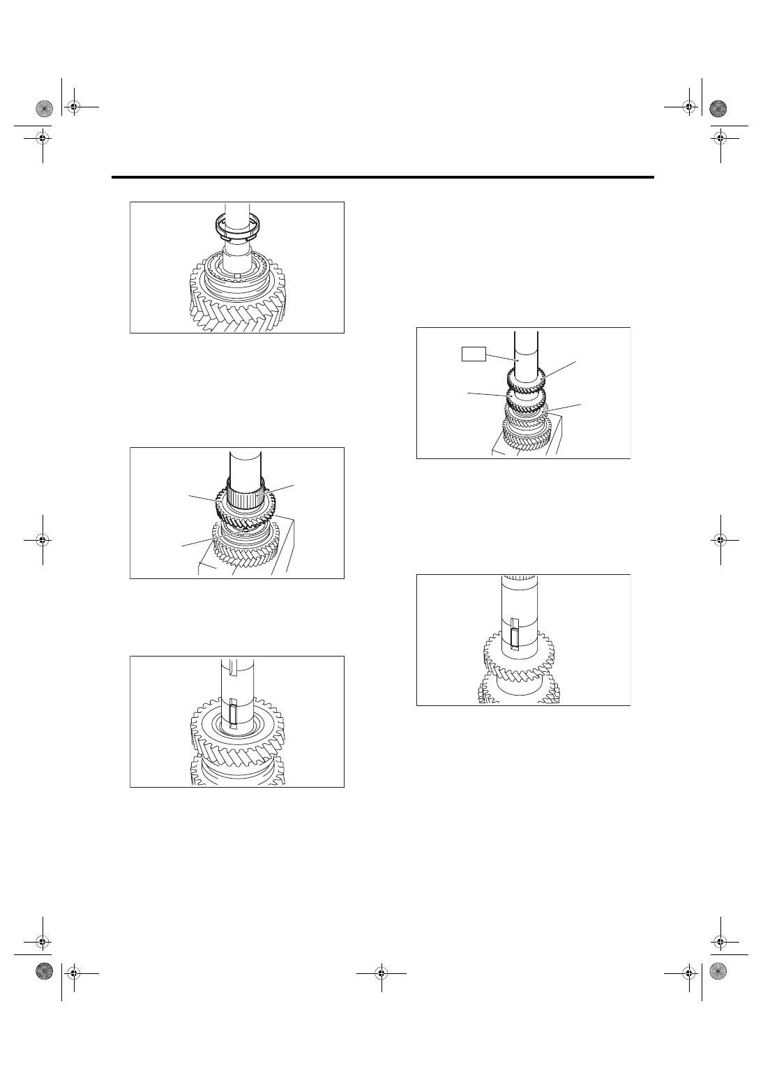
14) Install the inner baulk ring.
15) Apply adequate transmission gear oil to the
bushing, 2nd needle bearing and 2nd driven gear
inner surface.
16) Install the 2nd needle bearing and 2nd driven
gear.
NOTE:
Match the protrusion of the 2nd synchro cone to the
hole of the 2nd driven gear, then install.
17) Attach the key.
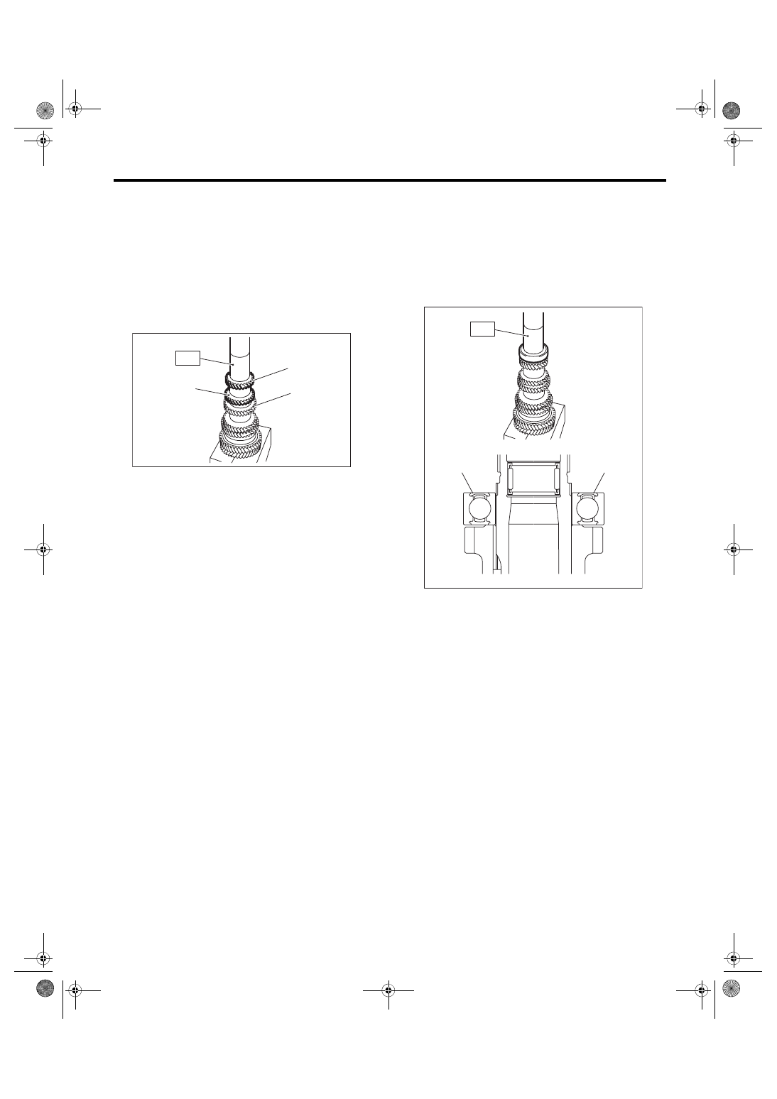
18) Using the ST, install the 3rd-4th driven gear.
ST 18654AA000 INSTALLER
CAUTION:
Do not apply pressure in excess of 40 kN (4.0
ton, 4.4 US ton, 3.9 Imp ton).
NOTE:
• Make sure that the 3rd-4th driven gear is in-
stalled in the correct direction.
• Match the groove on the 3rd-4th driven gear to
the key.
19) Make sure that the 2nd driven gear can be
turned smoothly by hand. If it does not turn smooth-
ly, reassemble.
20) Attach the key.
(A) 2nd needle bearing
(B) 2nd driven gear
(C) Protrusion of the 2nd synchro cone
MT-00606
MT-00607
(A)
(C)
(B)
MT-00608
(A) 4th gear
(B) 3rd gear
(C) 2nd gear
MT-00609
(A)
(C)
(B)
ST
MT-00610
6MT-86
Driven Gear Assembly
MANUAL TRANSMISSION AND DIFFERENTIAL
21) Using the ST, install the 5th-6th driven gear.
ST 18654AA000 INSTALLER
CAUTION:
Do not apply pressure in excess of 40 kN (4.0
ton, 4.4 US ton, 3.9 Imp ton).
NOTE:
• Make sure that the 5th-6th driven gear is in-
stalled in the correct direction.
• Match the groove on the 5th-6th driven gear to
the key.
22) Using the ST, install the ball bearing.
ST 18654AA000 INSTALLER
CAUTION:
Do not apply pressure in excess of 40 kN (4.0
ton, 4.4 US ton, 3.9 Imp ton).
NOTE:
Face the sealing section of the ball bearing to the
lock nut side, and install the ball bearing.
23) Make sure that the ball bearing turns smoothly
by hand. If it does not turn smoothly, reassemble.
24) Install a new lock nut.
(A) 6th gear
(B) 5th gear
(C) 4th gear
MT-00611
(B)
ST
(A)
(C)
(A) Sealing
MT-02108
ST
(A)
(A)
6MT-87
Driven Gear Assembly
MANUAL TRANSMISSION AND DIFFERENTIAL
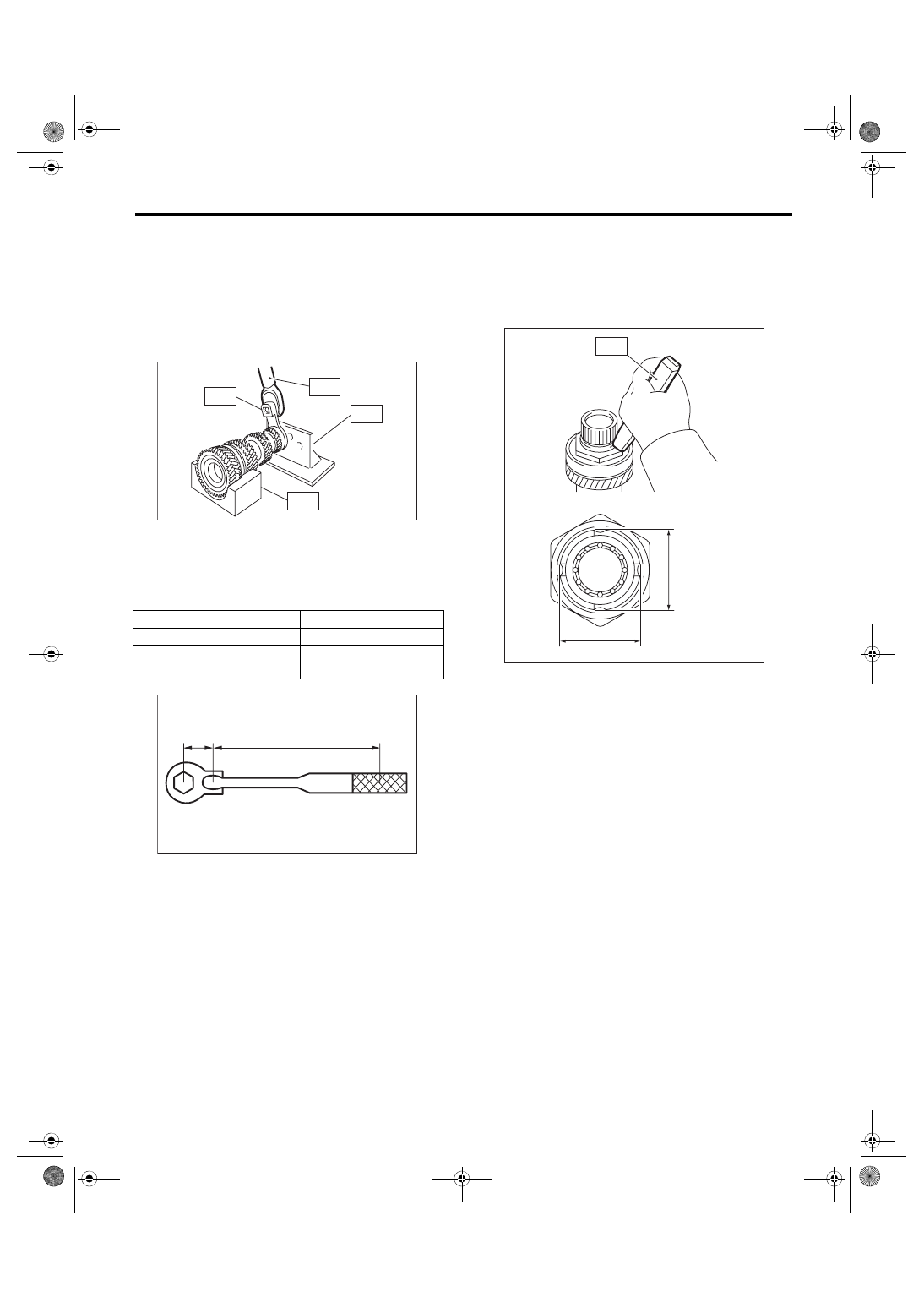
25) Attach ST3 to the lock nut, attach ST to the driv-
en gear assembly, and tighten the lock nut.
ST1 18666AA000
HOLDER
ST2 18664AA000
BASE
ST3 18620AA000
ADAPTER WRENCH
ST4 18852AA000
TORQUE WRENCH
Tightening torque:
530 N·m (54.0 kgf-m, 390.9 ft-lb)
NOTE:
When using a torque wrench other than ST4, use
the calculation below to calculate and tighten the
lock nut.
T = L1/(0.1 + L1) × 570
26) Using the ST, crimp the lock nut in 4 locations,
with dimensions within A 44±0.5 mm (1.73±0.02
in).
ST 18669AA000 PUNCH DRIVEN SHAFT
NOTE:
Do not damage the crimp area of the lock nut.
E: INSPECTION
Disassembled parts should be washed with clean-
ing solvent first, then inspected carefully.
1) Bearing
Replace the bearings in the following cases.
• Wear, rusting or damage of the bearings
• The bearing does not rotate smoothly or an ab-
normal noise is emitted when turning.
• The bearing has other defects.
2) Bushing (each gear)
Replace the bushing in following cases.
• The sliding surface is damaged or abnormally
worn.
3) Gear
Replace gears in the following cases.
• The gear teeth surface is damaged or excessive-
ly worn.
• The contact area of the baulk ring is damaged.
• The inner face of the gear is worn.
4) Baulk ring, synchro cone
Replace the baulk ring and synchro cone in the fol-
lowing cases.
• Wear, rusting or damage of the baulk ring
T
N·m (kgf-m, ft-lb) Torque wrench setting
L1
m (in) Torque wrench length
0.1 m (3.94 in)
Length of ST
570 N·m (58.1 kgf-m, 420 ft-lb) Tightening torque (lock nut)
(A) 0.1 m (3.94 in)
MT-00613
ST1
ST2
ST4
ST3
MT-00614
(A)
L1
MT-00615
A
A
ST
6MT-88
Driven Gear Assembly
MANUAL TRANSMISSION AND DIFFERENTIAL
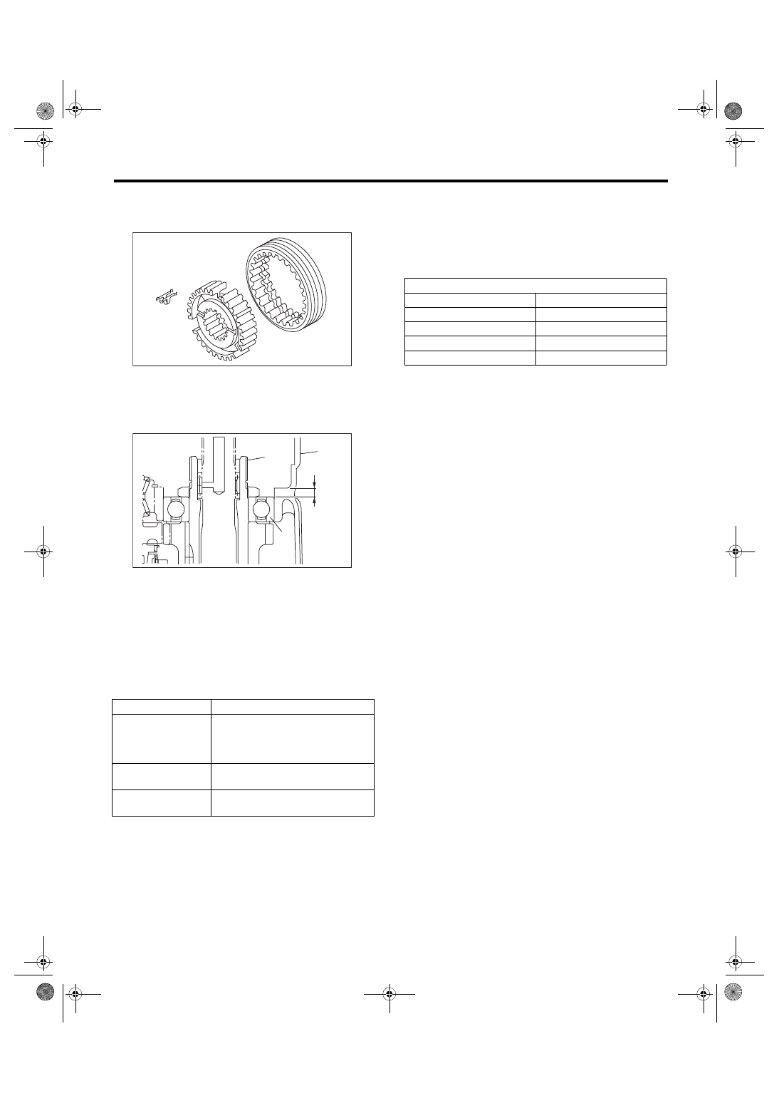
5) Shifting insert key
Replace the shifting insert key if deformed, exces-
sively worn or defective in any way.
F: ADJUSTMENT
1) Measure the length “H” from the transmission
case and transfer bearing holder mating surface, to
the end face of the ball bearing.
2) Using the following calculation, calculate the
thickness of the driven gear assembly adjusting
washer.
T = H – {5.8±0.05 mm (0.23±0.002 in)} – {0.1 — 0.3
mm (0.0039 — 0.0118 in)}
3) Select 0 to 3 adjusting washers from the follow-
ing table, and adjust to the backlash that is closest
to the standard value.
Driven gear assembly axial direction backlash
standard:
0.1 — 0.3 mm (0.0039 — 0.0118 in)
(A) Transmission case
(B) Ball bearing
(C) Driven gear ASSY
T
Adjusting washer thickness
H
Length from the transmission case
and transfer bearing holder mating
surface to the end face of the ball
bearing
5.8±0.05 mm
(0.23±0.002 in)
Collar thickness
0.1 — 0.3 mm
(0.0039 — 0.0118 in)
Driven gear assembly axial direc-
tion backlash standard
MT-00581
MT-00616
(A)
H
(C)
(B)
Adjusting washer
Part No.
Thickness T mm (in)
803072030
0.15 (0.0059)
803072031
0.30 (0.0118)
803072032
0.45 (0.0177)
803072033
0.60 (0.0236)
Нет комментариевНе стесняйтесь поделиться с нами вашим ценным мнением.
Текст