Subaru Impreza 3 / Impreza WRX / Impreza WRX STI. Service manual — part 436
6MT-81
Driven Gear Assembly
MANUAL TRANSMISSION AND DIFFERENTIAL
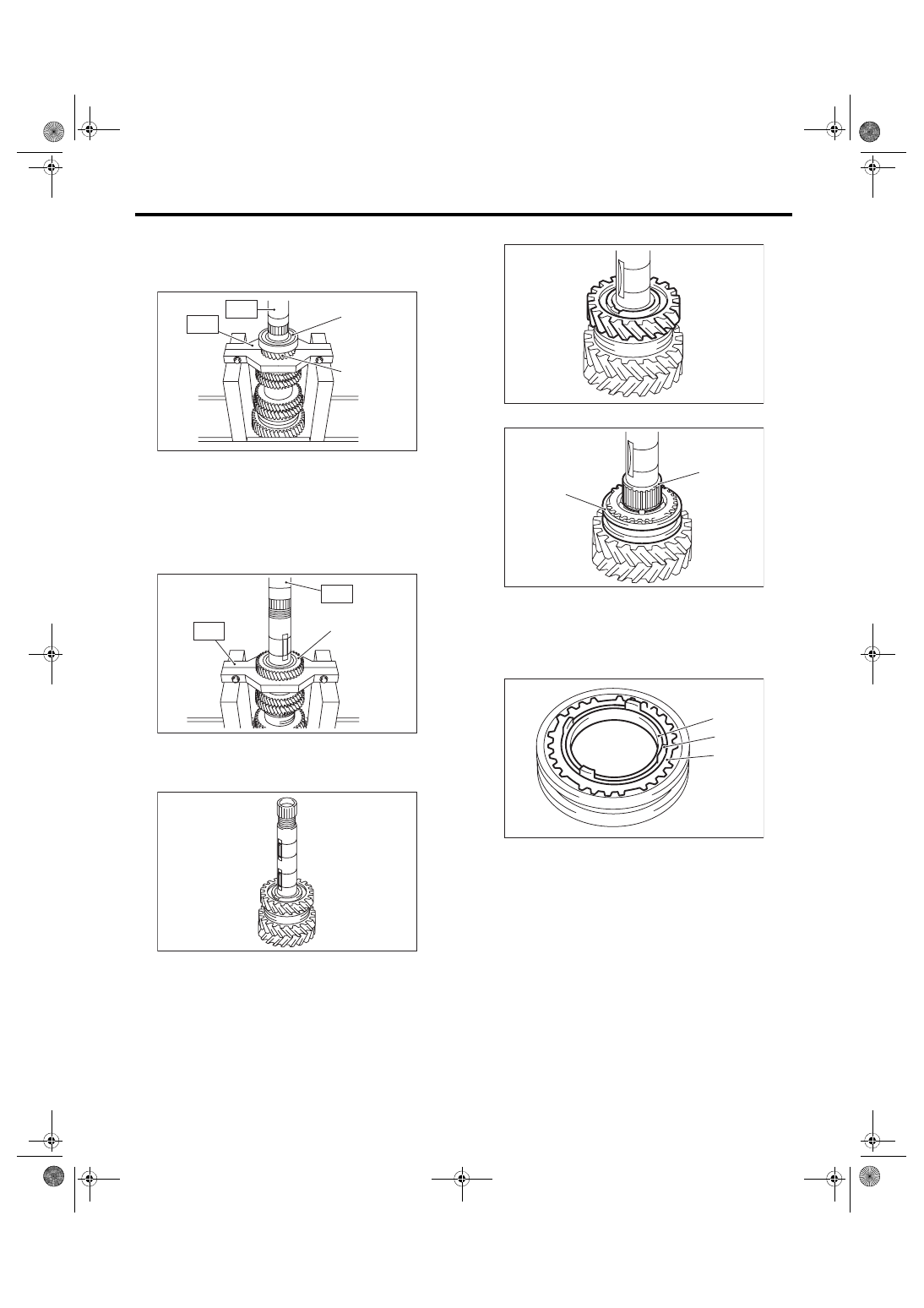
4) Attach ST1 to the 6th driven gear, then remove
the ball bearing and 5th-6th driven gear.
ST1 18723AA000
REMOVER
ST2 499877000
RACE 4-5 INSTALLER
5) Attach ST1 to the 4th driven gear, then remove
the 3rd-4th driven gear.
ST1 18723AA000
REMOVER
ST2 499877000
RACE 4-5 INSTALLER
6) Remove the driven gear key.
7) Remove the 2nd gear.
8) Remove the needle bearing and 1st-2nd sleeve.
9) Remove the outer baulk ring, 2nd synchro cone
and inner baulk ring.
(A) Ball bearing
(B) 5th-6th driven gear
(A) 3rd-4th driven gear
MT-01480
(A)
(B)
ST2
ST1
MT-01481
(A)
ST2
ST1
MT-00590
(A) Needle bearing
(B) 1st-2nd sleeve
(A) Outer baulk ring
(B) 2nd synchro cone
(C) Inner baulk ring
MT-00591
MT-00592
(A)
(B)
MT-01502
(B)
(A)
(C)
6MT-82
Driven Gear Assembly
MANUAL TRANSMISSION AND DIFFERENTIAL
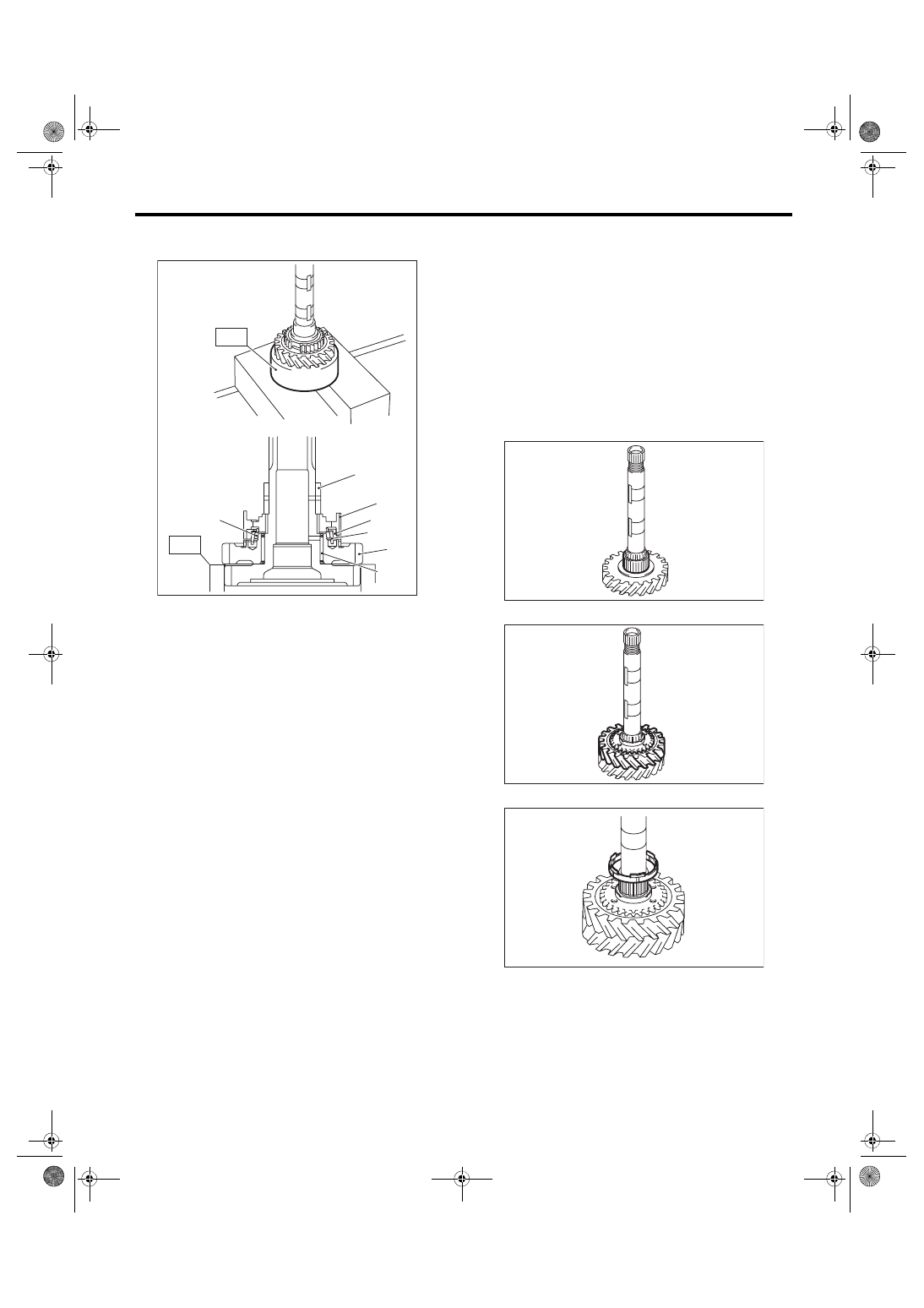
10) Using the ST, remove individual parts.
ST 18754AA000 REMOVER
D: ASSEMBLY
NOTE:
When replacing the following parts, replace as a
set.
• Sleeve and hub
• Outer baulk ring, 1st synchro cone and inner
baulk ring
• Outer baulk ring, 2nd synchro cone and inner
baulk ring
1) Apply adequate transmission gear oil to the main
shaft, 1st needle bearing and 1st driven gear inner
surface.
2) Install the 1st needle bearing.
3) Attach the 1st driven gear to the driven shaft.
4) Install the inner baulk ring.
(A) 2nd bushing
(B) 1st-2nd hub
(C) Outer baulk ring
(D) 1st synchro cone
(E) Inner baulk ring
(F) 1st driven gear
(G) 1st needle bearing
(A)
(E)
(B)
(C)
(D)
(F)
(G)
MT-01715
ST
ST
MT-00595
MT-01729
MT-01730
6MT-83
Driven Gear Assembly
MANUAL TRANSMISSION AND DIFFERENTIAL
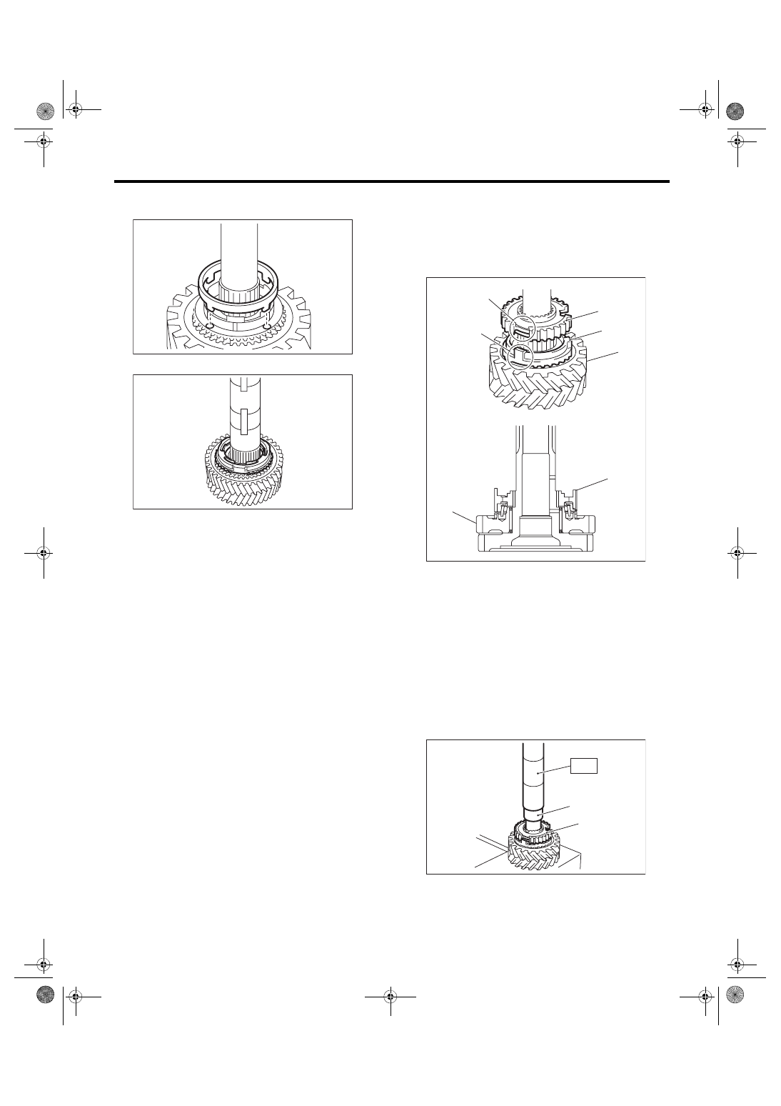
5) Match the protrusion of the 1st synchro cone to
the hole of the 1st driven gear, then install.
6) Install the outer baulk ring.
7) Install the 1st-2nd hub.
NOTE:
• Match the cut out of the 1st-2nd hub with the pro-
trusion on the outer baulk ring, then install.
• Make sure that the 1st-2nd hub is installed in the
correct direction.
8) Using the ST, install the 1st-2nd hub and 2nd
bush.
ST 18654AA000 INSTALLER
CAUTION:
Do not apply pressure in excess of 40 kN (4.0
ton, 4.4 US ton, 3.9 Imp ton).
MT-01505
MT-00599
(A) 1st-2nd hub
(B) Outer baulk ring
(C) 1st-2nd hub cut out section
(D) Protrusion of the outer baulk ring
(E) 1st driven gear
(A) 2nd bushing
(B) 1st-2nd hub
MT-01716
(E)
(D)
(C)
(A)
(B)
(E)
(A)
MT-00601
(B)
(A)
ST
6MT-84
Driven Gear Assembly
MANUAL TRANSMISSION AND DIFFERENTIAL
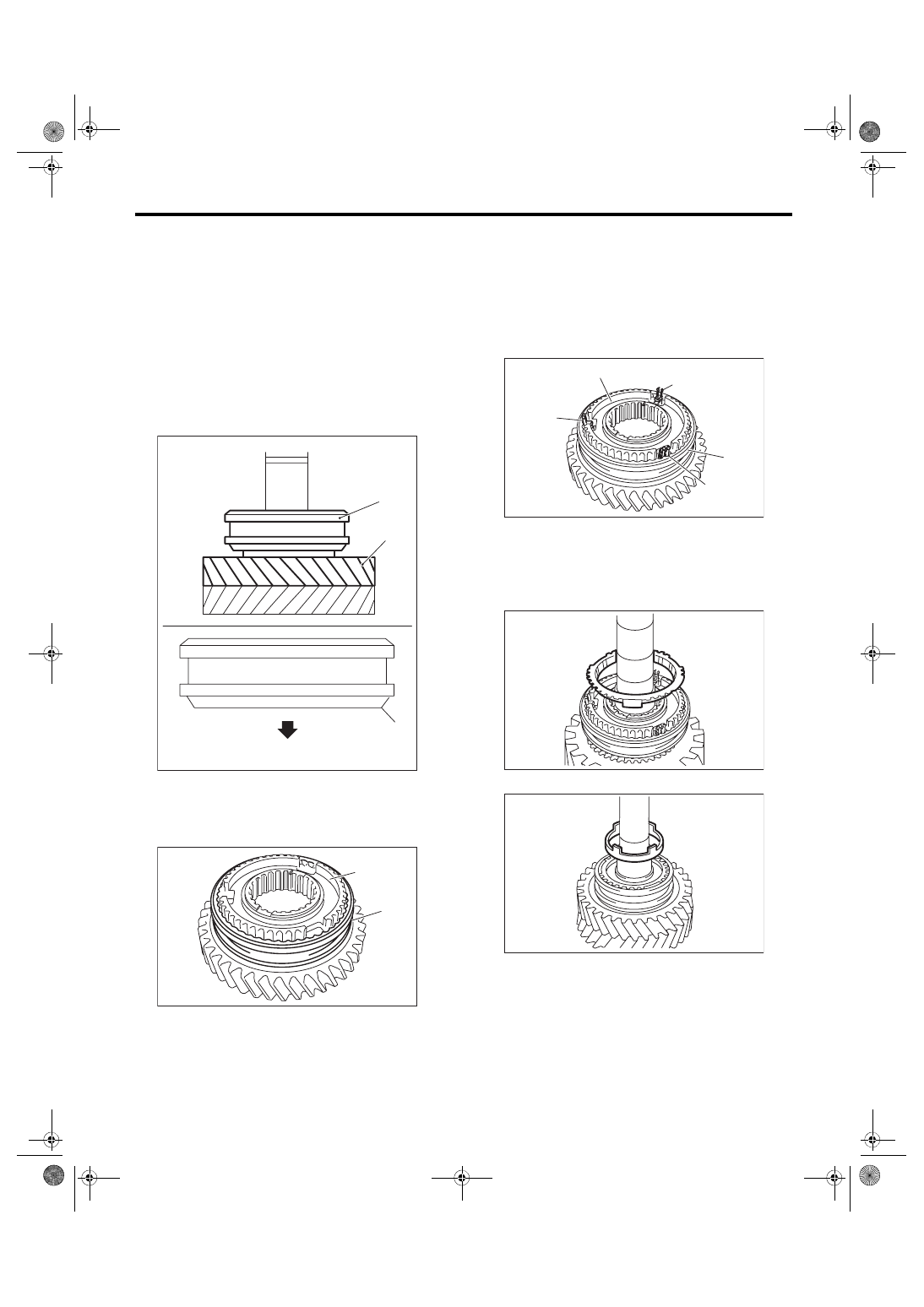
9) Make sure that the 1st driven gear can be turned
smoothly by hand. If it does not turn smoothly, re-
assemble.
10) Attach the 1st-2nd sleeve to the 1st-2nd hub.
NOTE:
• Make sure that the 1st-2nd sleeve is installed in
the correct direction.
• Align the 1st-2nd hub cut out section (three plac-
es) and the key grooves (three places) of shifting
insert key that are located inside the 1st-2nd
sleeve.
• Set the 1st-2nd sleeve and 1st driven gear so
that they contact each other.
11) Attach the shifting insert key to the appropriate
position of the 1st-2nd sleeve.
NOTE:
• The location angle of each shifting insert key is
120°.
• Install the shifting insert key to the key grooves
(three places) of shifting insert key that are located
inside the 1st-2nd sleeve.
12) Install the outer baulk ring.
13) Install the 2nd synchro cone.
(A) 1st driven gear
(B) 1st-2nd sleeve
(C) 1st driven gear side
(A) 1st-2nd hub
(B) 1st-2nd sleeve
MT-00603
(B)
(A)
(C)
(B)
MT-01731
(A)
(B)
(A) Shifting insert key
(B) 1st-2nd hub
(C) 1st-2nd sleeve
MT-01732
(A)
(B)
(C)
(A)
(A)
MT-01733
MT-01506
Нет комментариевНе стесняйтесь поделиться с нами вашим ценным мнением.
Текст