Subaru Impreza 3 / Impreza WRX / Impreza WRX STI. Service manual — part 406
5MT-45
Center Differential
MANUAL TRANSMISSION AND DIFFERENTIAL
12.Center Differential
A: REMOVAL
1) Remove the manual transmission assembly
from the vehicle. <Ref. to 5MT-23, REMOVAL,
Manual Transmission Assembly.>
2) Remove the back-up light switch and the neutral
position switch. <Ref. to 5MT-33, REMOVAL,
3) Remove the transfer case together with the ex-
tension case assembly. <Ref. to 5MT-35, REMOV-
AL, Transfer Case and Extension Case
4) Remove the extension case assembly. <Ref. to
5MT-35, REMOVAL, Transfer Case and Extension
5) Remove the transfer driven gear. <Ref. to 5MT-
43, REMOVAL, Transfer Driven Gear.>
6) Remove the center differential.
B: INSTALLATION
1) Attach the center differential to transfer case.
2) Install the transfer driven gear. <Ref. to 5MT-43,
INSTALLATION, Transfer Driven Gear.>
3) Install the extension case assembly. <Ref. to
5MT-35, INSTALLATION, Transfer Case and Ex-
4) Install the transfer case together with the exten-
sion case assembly. <Ref. to 5MT-35, INSTALLA-
TION, Transfer Case and Extension Case
5) Install the back-up light switch and the neutral
position switch. <Ref. to 5MT-33, INSTALLATION,
6) Install the manual transmission assembly to the
vehicle. <Ref. to 5MT-26, INSTALLATION, Manual
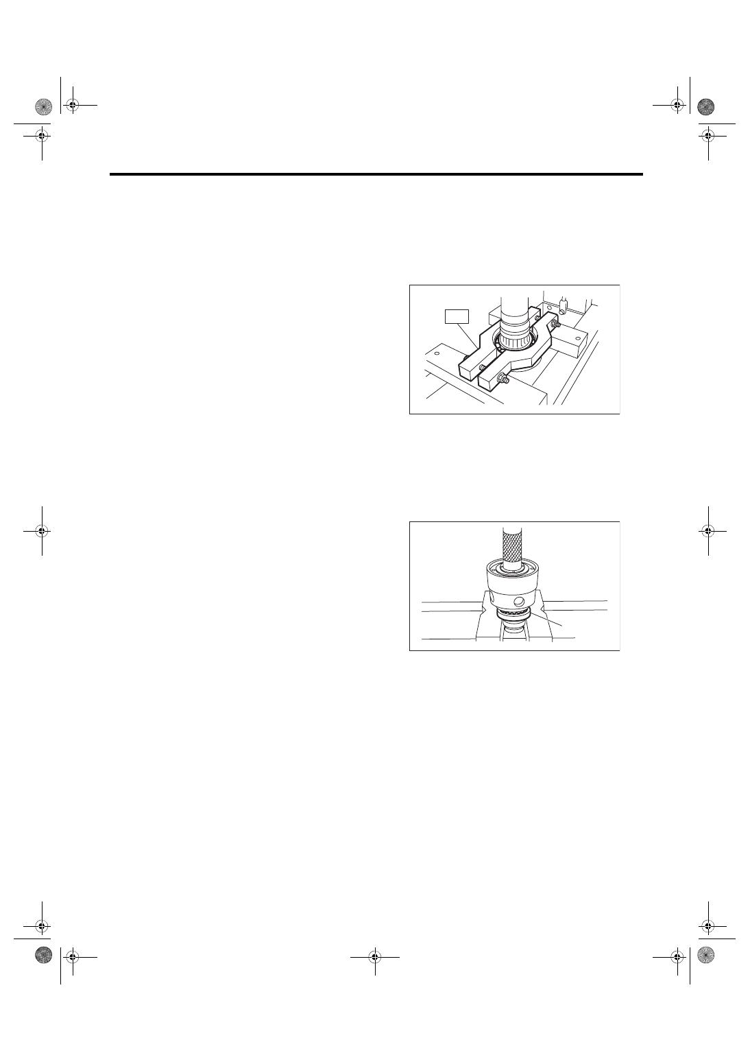
C: DISASSEMBLY
Remove the ball bearing using ST.
NOTE:
Center differential is a non-disassembled part
which should not be disassembled.
ST 498077300
CENTER DIFFERENTIAL
BEARING REMOVER
D: ASSEMBLY
Install the ball bearing to the center differential as-
sembly.
CAUTION:
• Do not apply a load in excess of 10 kN (1 ton,
1.1 US ton, 1.0 Imp ton).
• Use a new ball bearing.
E: INSPECTION
1) Bearing
Replace the bearings in the following cases.
• In case of broken or rusty bearings
• In case of worn or damaged bearings
• When the bearings fail to turn smoothly or emit
noise in rotation after gear oil lubrication.
• When bearing has other defects.
2) Center differential
If there is wear or damage, replace the center dif-
ferential case assembly.
(A) Ball bearing
MT-00147
ST
MT-00148
(A)
5MT-46
Reverse Check Sleeve
MANUAL TRANSMISSION AND DIFFERENTIAL
13.Reverse Check Sleeve
A: REMOVAL
1) Remove the manual transmission assembly
from the vehicle. <Ref. to 5MT-23, REMOVAL,
Manual Transmission Assembly.>
2) Remove the transfer case together with the ex-
tension case assembly. <Ref. to 5MT-35, REMOV-
AL, Transfer Case and Extension Case
3) Remove the shifter arm.
4) Remove the plug, gasket, reverse accent spring,
and reverse check ball.
5) Remove the reverse check sleeve.
B: INSTALLATION
1) Install the reverse check sleeve.
Tightening torque:
6.4 N·m (0.7 kgf-m, 4.7 ft-lb)
2) Install the reverse check ball, reverse accent
spring, gasket, and plug to the transfer case.
NOTE:
Use a new gasket.
Tightening torque:
9.75 N·m (1.0 kgf-m, 7.2 ft-lb)
3) Attach the shifter arm to the transfer case as-
sembly.
4) Install the transfer case together with the exten-
sion case assembly. <Ref. to 5MT-35, INSTALLA-
TION, Transfer Case and Extension Case
5) Install the manual transmission assembly to the
vehicle. <Ref. to 5MT-26, INSTALLATION, Manual
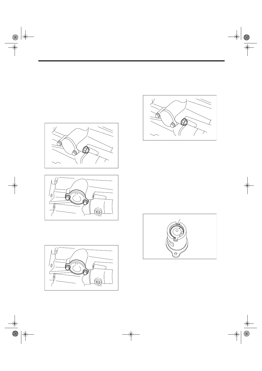
C: DISASSEMBLY
1) Cover the reverse check sleeve with cloth, and
remove the snap ring by using screwdriver.
NOTE:
If the snap ring is deformed or the spring repulsive
force is not enough, replace with a new snap ring.
MT-00149
MT-00150
MT-00150
(A) Snap ring
MT-00149
MT-00153
(A)
5MT-47
Reverse Check Sleeve
MANUAL TRANSMISSION AND DIFFERENTIAL
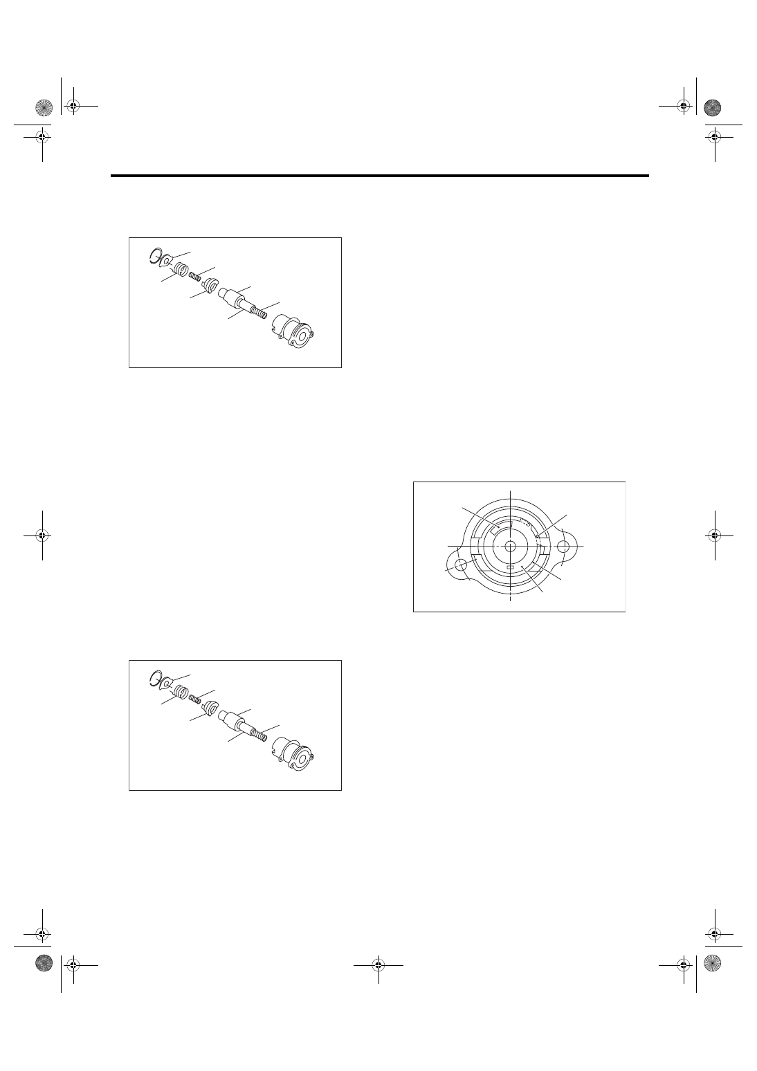
2) Remove the reverse check plate, reverse check
spring, reverse check cam, return spring (5th-Re-
verse), reverse accent shaft, return spring cap, and
return spring (1st-2nd).
3) Remove the O-ring.
NOTE:
Be careful not to damage the adjusting shim be-
tween reverse check sleeve assembly and case.
D: ASSEMBLY
1) Install the return spring (1st-2nd), return spring
cap, reverse accent shaft, reverse check cam, re-
turn spring (5th-Reverse) and reverse check spring
to the reverse check sleeve.
NOTE:
Be sure to insert the curved part of reverse check
spring into the check cam groove.
2) Hook the curved part of reverse check spring
onto the reverse check plate.
3) Rotate the cam so that the protrusion on the re-
verse check cam is located at the plate opening.
4) While fixing the cam to that position, attach the
reverse check plate to the reverse check sleeve,
and secure with snap ring.
5) Insert the O-ring into the sleeve groove.
NOTE:
Use new O-rings.
E: INSPECTION
• Make sure the cutout of the reverse accent shaft
is aligned with the opening in the reverse check
sleeve.
• Turn the cam by hand to check for smooth rota-
tion.
• Move the cam and shaft all the way toward the
plate, and make sure it releases.
If the cam does not return properly, replace the re-
verse check spring. If the shaft does not return,
check for scratches on the inner surface of sleeve.
If the sleeve is in good order, replace the spring.
• Select a suitable reverse accent shaft and re-
verse check plate. <Ref. to 5MT-48, ADJUST-
(A) Reverse check plate
(B) Reverse check spring
(C) Return spring (5th-Reverse)
(D) Reverse check cam
(E) Reverse accent shaft
(F) Return spring cap
(G) Return spring (1st-2nd)
(A) Reverse check plate
(B) Reverse check spring
(C) Return spring (5th-Reverse)
(D) Reverse check cam
(E) Reverse accent shaft
(F) Return spring cap
(G) Return spring (1st-2nd)
MT-00154
(B)
(C)
(D)
(E)
(F)
(G)
(A)
MT-00154
(B)
(C)
(D)
(E)
(F)
(G)
(A)
(A) Snap ring
(B) Reverse check plate
(C) Reverse check spring
(D) Reverse check cam
MT-00156
(A)
(D)
(B)
(C)
5MT-48
Reverse Check Sleeve
MANUAL TRANSMISSION AND DIFFERENTIAL
F: ADJUSTMENT
1. NEUTRAL POSITION ADJUSTMENT
1) Shift the gear into 3rd gear position.
2) Because of the return spring, until the arm con-
tacts the stopper the shifter arm will feel lighter
moving towards 1st/2nd gear and heavier towards
the reverse gear.
3) Make adjustment so that the heavy stroke (re-
verse side) is a little heavier than the lighter stroke
(1st/2nd side).
4) To adjust, remove the bolts holding the reverse
check sleeve assembly to the case, and move the
sleeve assembly outward, then place an adjust-
ment shim between the sleeve assembly and the
case to adjust the clearance.
CAUTION:
Be careful not to damage the O-ring when plac-
ing shims.
NOTE:
• When the shim is removed, the neutral position
will move closer to reverse; when the shim is add-
ed, the neutral position will move closer to 1st gear.
• If it is not possible to adjust the clearance with
only shims, replace the reverse accent shaft and
re-adjust.
2. REVERSE CHECK PLATE ADJUST-
MENT
1) Shift the shifter arm to “5th” and then to reverse
to see if the reverse check mechanism operates
properly.
2) Also check to see if the arm returns to neutral
when released from the reverse position. If the arm
does not return properly, replace the reverse check
plate.
Adjusting shim
Part No.
Thickness mm (in)
32190AA000
0.15 (0.0059)
32190AA010
0.30 (0.0118)
Reverse accent shaft
Part No.
Mark
Remarks
32188AA130
S
Neutral position is closer to
1st gear.
32188AA140
T
Standard
32188AA150
U
Neutral position is closer to
reverse gear.
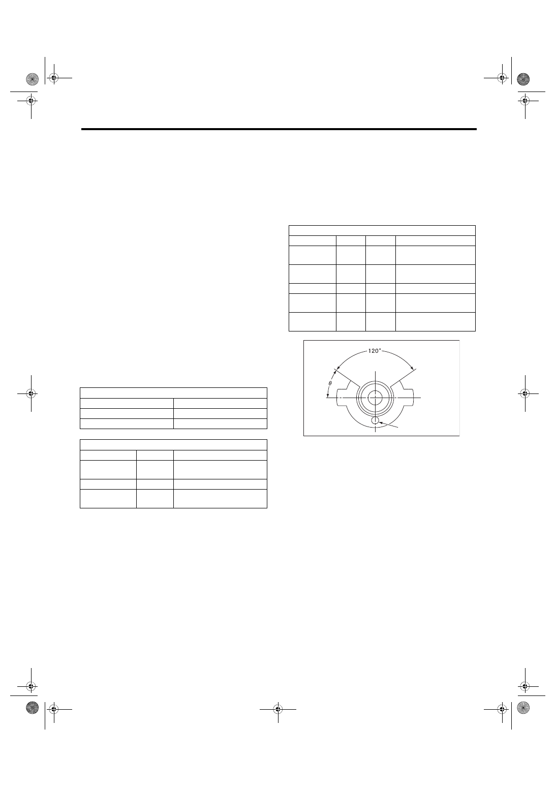
Reverse check plate
Part No.
(A): No. Angle θ
Remarks
32189AA001
0
28°
Arm stops closer to 5th
gear.
32189AA011
1
31°
Arm stops closer to 5th
gear.
32189AA021
2
34°
Arm stops in the center.
32189AA031
3
37°
Arm stops closer to
reverse gear.
32189AA041
4
40°
Arm stops closer to
reverse gear.
MT-00157
(A)
Нет комментариевНе стесняйтесь поделиться с нами вашим ценным мнением.
Текст