Subaru Impreza 3 / Impreza WRX / Impreza WRX STI. Service manual — part 404
5MT-37
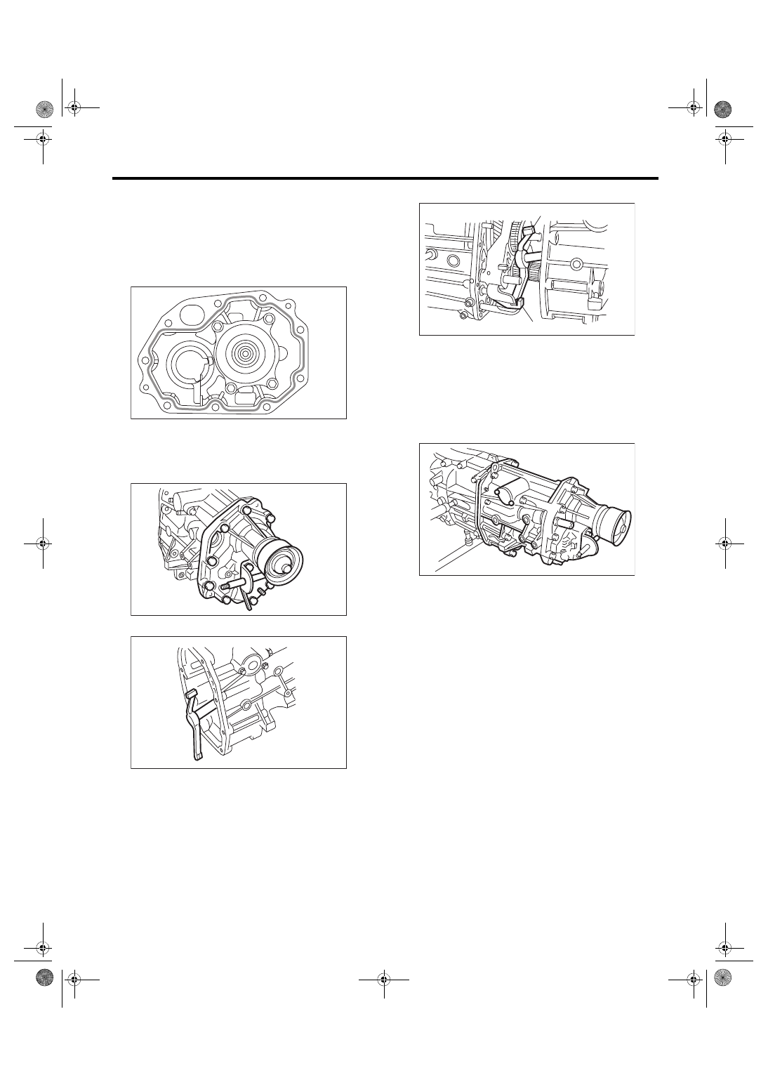
Transfer Case and Extension Case Assembly
MANUAL TRANSMISSION AND DIFFERENTIAL
15) Install the adjusting washer to center differen-
tial.
16) Apply a proper amount of liquid gasket to the
transfer case mating surface.
Liquid gasket:
THREE BOND 1215 (Part No. 004403007) or
equivalent
17) Attach the extension assembly to the transfer
case.
Tightening torque:
40 N·m (4.1 kgf-m, 29.5 ft-lb)
18) Attach the shifter arm to transfer case.
19) Attach the gasket.
NOTE:
Use a new gasket.
20) Hang the shifter arm on 3rd-4th fork rod.
21) Install the extension case assembly along with
the transfer case to the transmission case.
Tightening torque:
24.5 N·m (2.5 kgf-m, 18.1 ft-lb)
MT-00124
MT-00117
MT-00126
(A) Shifter arm
(B) 3rd-4th fork rod
MT-00127
(A)
(B)
MT-02614
5MT-38
Transfer Case and Extension Case Assembly
MANUAL TRANSMISSION AND DIFFERENTIAL
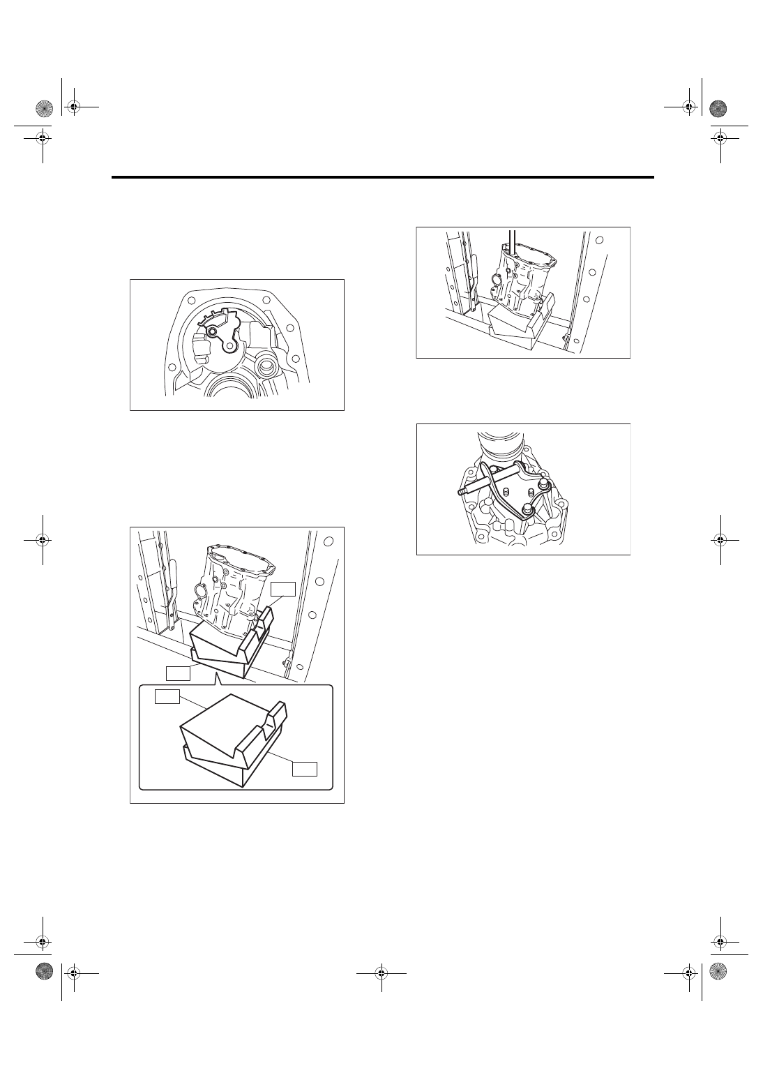
C: DISASSEMBLY
1. TRANSFER CASE
1) Remove the reverse check sleeve assembly.
<Ref. to 5MT-46, REMOVAL, Reverse Check
2) Remove the oil guide.
3) Remove the oil seal.
4) Set ST1, ST2 and transfer case to a press.
NOTE:
• Set the ST2 under ST1.
• Set the transfer case so that the hole for shifter
arm is positioned vertically.
ST1 498267300
CYLINDER HEAD TABLE
ST2 498267200
CYLINDER HEAD TABLE
5) Using the round bar with diameter of 22 mm
(0.87 in) or 23 mm (0.91 in), remove the roller bear-
ing.
2. EXTENSION CASE
1) Remove the transfer drive gear assembly. <Ref.
to 5MT-41, REMOVAL, Transfer Drive Gear.>
2) Remove the shift bracket.
3) Remove the oil seal from the extension case.
MT-01563
MT-02138
ST1
ST2
ST2
ST1
MT-02139
MT-00130
5MT-39
Transfer Case and Extension Case Assembly
MANUAL TRANSMISSION AND DIFFERENTIAL
D: ASSEMBLY
1. EXTENSION CASE
1) Using the ST, install the oil seal to the extension
case. <Ref. to 5MT-31, Oil Seal.>
NOTE:
Use a new oil seal.
2) Install the shift bracket to extension case.
Tightening torque:
24.5 N·m (2.5 kgf-m, 18.1 ft-lb)
3) Install the transfer drive gear to the extension
case. <Ref. to 5MT-41, INSTALLATION, Transfer
2. TRANSFER CASE
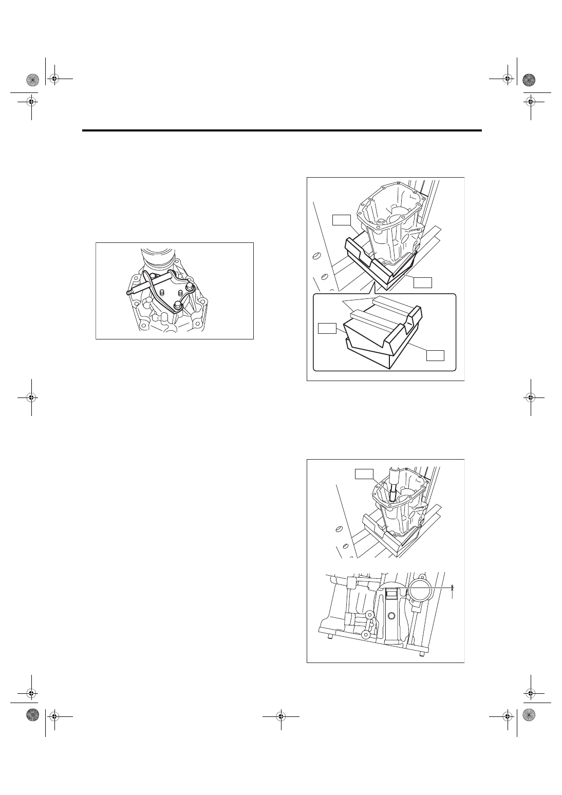
1) Set the ST1, ST2, iron plate and the transfer
case to the press.
NOTE:
• Set the ST2 under ST1.
• Set the transfer case so that the hole for shifter
arm is positioned vertically.
• Insert the iron plate which is thicker than the ex-
posed length of the transfer case knock pin be-
tween the ST and transfer case.
• Set the iron plate so that the transfer case knock
pin does not ride on the iron plate.
ST1 498267300
CYLINDER HEAD TABLE
ST2 498267200
CYLINDER HEAD TABLE
2) Press-fit the roller bearing using the ST.
Press-fit depth of needle bearing:
A: 0
±
0.2 mm (0
±
0.01 in) from the end of trans-
fer case
ST 899864100
REMOVER
MT-00130
(A) Iron plate
MT-02141
(A)
ST2
ST2
ST1
ST1
MT-02142
ST
A
5MT-40
Transfer Case and Extension Case Assembly
MANUAL TRANSMISSION AND DIFFERENTIAL
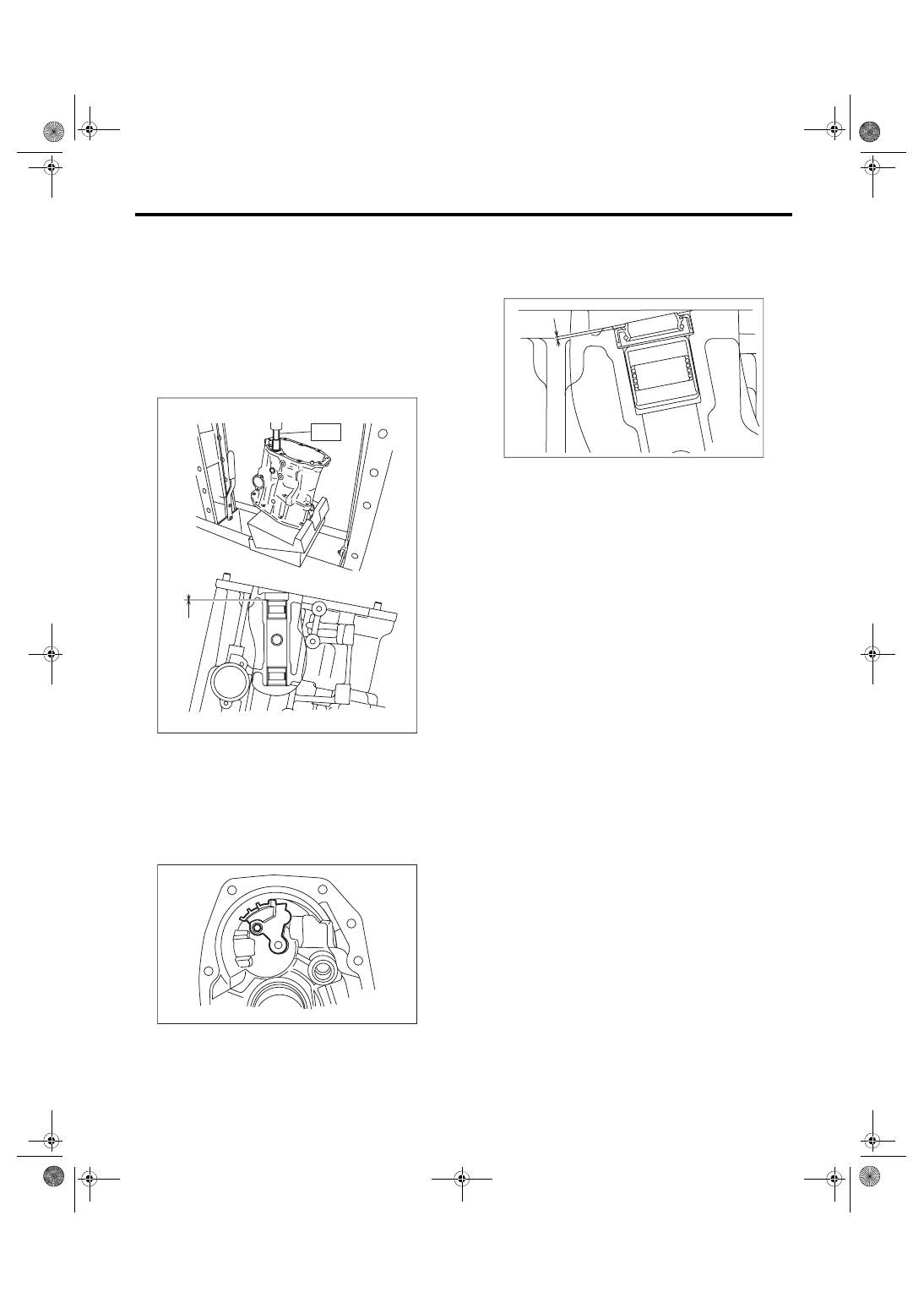
3) Remove the iron plate, and turn over the transfer
case.
NOTE:
Set the transfer case so that the hole for shifter arm
is positioned vertically.
4) Press-fit the roller bearing using the ST.
Press-fit depth of needle bearing:
A: 0
±
0.2 mm (0
±
0.01 in) from the end of trans-
fer case
ST 899864100
REMOVER
5) Install the shifter arm to the transfer case, and
make sure that the shift arm moves smoothly.
6) Install the oil guide to the transfer case.
NOTE:
Use a new installing bolt.
Tightening torque:
6.4 N·m (0.7 kgf-m, 4.7 ft-lb)
7) Install the reverse check sleeve assembly to the
transfer case. <Ref. to 5MT-46, INSTALLATION,
8) Install the oil seal.
Press-fit depth of oil seal:
A: 1
±
0.2 mm (0.04
±
0.01 in) from the end of
transfer case
MT-02140
ST
A
MT-01563
MT-02299
A
Нет комментариевНе стесняйтесь поделиться с нами вашим ценным мнением.
Текст