Subaru Impreza 3 / Impreza WRX / Impreza WRX STI. Service manual — part 405
5MT-41
Transfer Drive Gear
MANUAL TRANSMISSION AND DIFFERENTIAL
10.Transfer Drive Gear
A: REMOVAL
1) Remove the manual transmission assembly
from the vehicle. <Ref. to 5MT-23, REMOVAL,
Manual Transmission Assembly.>
2) Remove the back-up light switch and the neutral
position switch. <Ref. to 5MT-33, REMOVAL,
3) Remove the transfer case together with the ex-
tension case assembly. <Ref. to 5MT-35, REMOV-
AL, Transfer Case and Extension Case
4) Remove the extension case assembly.
5) Remove the transfer driven gear.
6) Remove the transfer drive gear.
B: INSTALLATION
1) Install the transfer drive gear.
Tightening torque:
26 N·m (2.7 kgf-m, 19.2 ft-lb)
2) Select the adjusting washer. <Ref. to 5MT-35,
INSTALLATION, Transfer Case and Extension
3) Install the transfer driven gear.
4) Install the extension case assembly.
5) Install the transfer case and the extension case
assembly. <Ref. to 5MT-35, INSTALLATION,
Transfer Case and Extension Case Assembly.>
6) Install the back-up light switch and the neutral
position switch. <Ref. to 5MT-33, INSTALLATION,
7) Install the manual transmission assembly to the
vehicle. <Ref. to 5MT-26, INSTALLATION, Manual
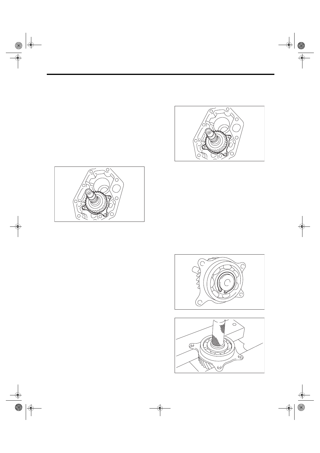
C: DISASSEMBLY
1) Remove the snap ring.
2) Remove the ball bearing.
MT-00133
MT-00133
MT-00135
MT-00136
5MT-42
Transfer Drive Gear
MANUAL TRANSMISSION AND DIFFERENTIAL
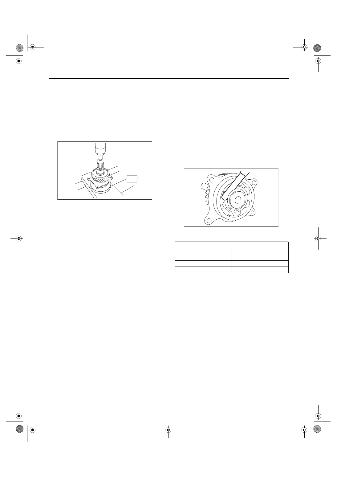
D: ASSEMBLY
1) Set the ST against the inner race of the bearing,
and install the drive shaft.
ST 398177700
INSTALLER
CAUTION:
Do not apply a load in excess of 10 kN (1 ton, 1.1
US ton, 1.0 Imp ton).
NOTE:
Use a new ball bearing.
2) Install the snap ring on the transfer drive shaft.
3) Inspect the clearance between the snap ring and
the ball bearing. <Ref. to 5MT-42, INSPECTION,
E: INSPECTION
1) Bearing
Replace the bearings in the following cases.
• In case of broken or rusty bearings
• In case of worn or damaged bearings
• When the bearings fail to turn smoothly or emit
noise in rotation after gear oil lubrication.
2) Drive gear
If the drive gear tooth surface and shaft are exces-
sively broken or damaged, replace the drive gear.
3) Measure the clearance between snap ring and
inner race of ball bearing with a thickness gauge.
Clearance:
0.01 — 0.15 mm (0.0004 — 0.0059 in)
If the measurement is not within specification, se-
lect a suitable snap ring and replace it.
MT-00137
ST
Snap ring (outer-30)
Part No.
Thickness mm (in)
805030041
1.53 (0.0602)
805030042
1.65 (0.0650)
805030043
1.77 (0.0697)
MT-00138
5MT-43
Transfer Driven Gear
MANUAL TRANSMISSION AND DIFFERENTIAL
11.Transfer Driven Gear
A: REMOVAL
1) Remove the manual transmission assembly
from the vehicle. <Ref. to 5MT-23, REMOVAL,
Manual Transmission Assembly.>
2) Remove the back-up light switch and the neutral
position switch. <Ref. to 5MT-33, REMOVAL,
3) Remove the transfer case together with the ex-
tension case assembly. <Ref. to 5MT-35, REMOV-
AL, Transfer Case and Extension Case
4) Remove the extension case assembly.
5) Remove the transfer driven gear.
6) Remove bearing outer races from the extension
case and transfer case.
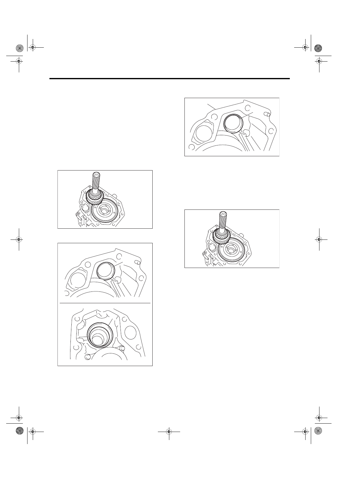
B: INSTALLATION
1) Install the bearing outer race to transfer case.
2) Apply a coat of grease to the front roller bearing
and rear roller bearing of the transfer driven gear.
Grease:
NICHIMOLY N-130 or equivalent
3) Install the transfer driven gear.
4) Select the adjusting washer. <Ref. to 5MT-35,
INSTALLATION, Transfer Case and Extension
5) Install the transfer case and the extension case
assembly. <Ref. to 5MT-35, INSTALLATION,
Transfer Case and Extension Case Assembly.>
6) Install the back-up light switch and the neutral
position switch. <Ref. to 5MT-33, INSTALLATION,
7) Install the manual transmission assembly to the
vehicle. <Ref. to 5MT-26, INSTALLATION, Manual
(A) Bearing outer race (transfer case side)
(B) Bearing outer race (extension case side)
MT-00118
MT-00140
(B)
(A)
(A) Bearing outer race
(B) Transfer case
MT-02300
(A)
(B)
MT-00118
5MT-44
Transfer Driven Gear
MANUAL TRANSMISSION AND DIFFERENTIAL
C: DISASSEMBLY
1) Using the ST, remove the roller bearing (exten-
sion case side).
ST 498077000
REMOVER
2) Using ST1 and ST2, remove the roller bearing
(transfer case side).
ST1 498077000
REMOVER
ST2 899864100
REMOVER
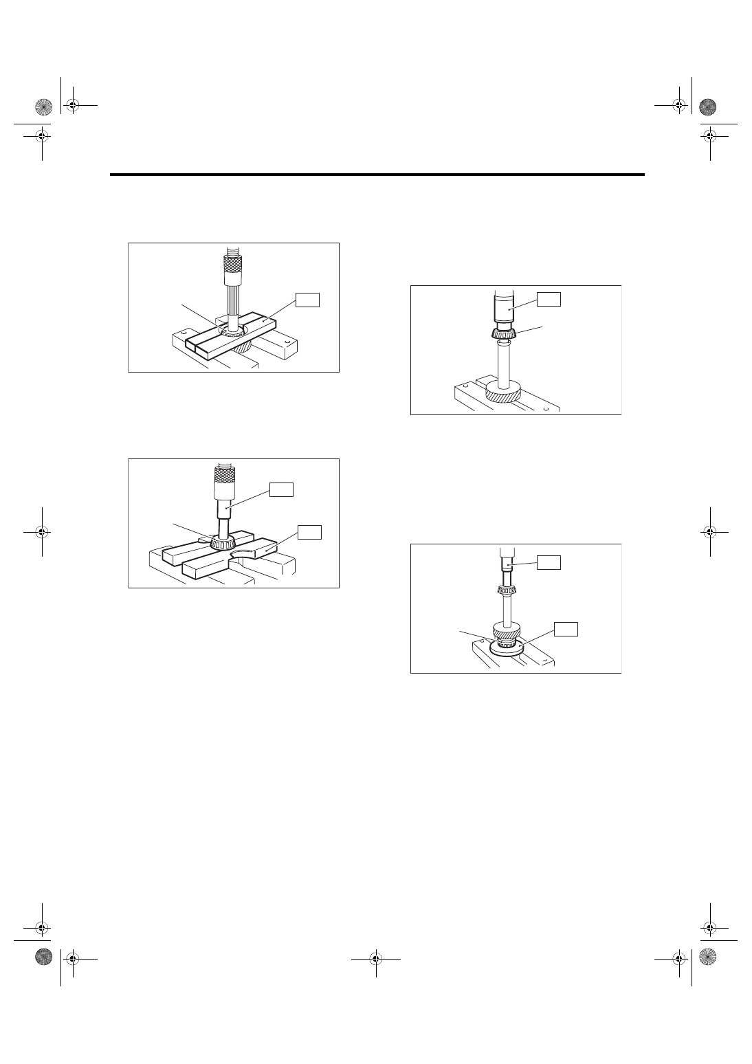
D: ASSEMBLY
1) Using ST, install the roller bearing (transfer case
side).
ST 927640000
INSTALLER
CAUTION:
Do not apply a load in excess of 10 kN (1 ton, 1.1
US ton, 1.0 Imp ton).
2) Using the ST, install the roller bearing (extension
case side).
ST1 498175500
INSTALLER
ST2 899864100
REMOVER
CAUTION:
Do not apply a load in excess of 10 kN (1 ton, 1.1
US ton, 1.0 Imp ton).
E: INSPECTION
1) Bearing
Replace the bearings in the following cases.
• In case of broken or rusty bearings
• In case of worn or damaged bearings
• When the bearings fail to turn smoothly or emit
noise in rotation after gear oil lubrication.
2) Driven gear
If the tooth face of driven gear and the shaft are ex-
cessively broken or damaged, replace the driven
gear.
(A) Roller bearing
(A) Roller bearing
MT-00143
(A)
ST
MT-00144
(A)
ST1
ST2
(A) Roller bearing
(A) Roller bearing
MT-00146
(A)
ST
MT-00145
(A)
ST1
ST2
Нет комментариевНе стесняйтесь поделиться с нами вашим ценным мнением.
Текст