Subaru Impreza 3 / Impreza WRX / Impreza WRX STI. Service manual — part 407
5MT-49
Transmission Case
MANUAL TRANSMISSION AND DIFFERENTIAL
14.Transmission Case
A: REMOVAL
1) Remove the manual transmission assembly
from the vehicle. <Ref. to 5MT-23, REMOVAL,
Manual Transmission Assembly.>
2) Remove the clutch release lever. <Ref. to CL-
15, REMOVAL, Release Bearing and Lever.>
3) Remove the transfer case together with the ex-
tension case assembly. <Ref. to 5MT-35, REMOV-
AL, Transfer Case and Extension Case
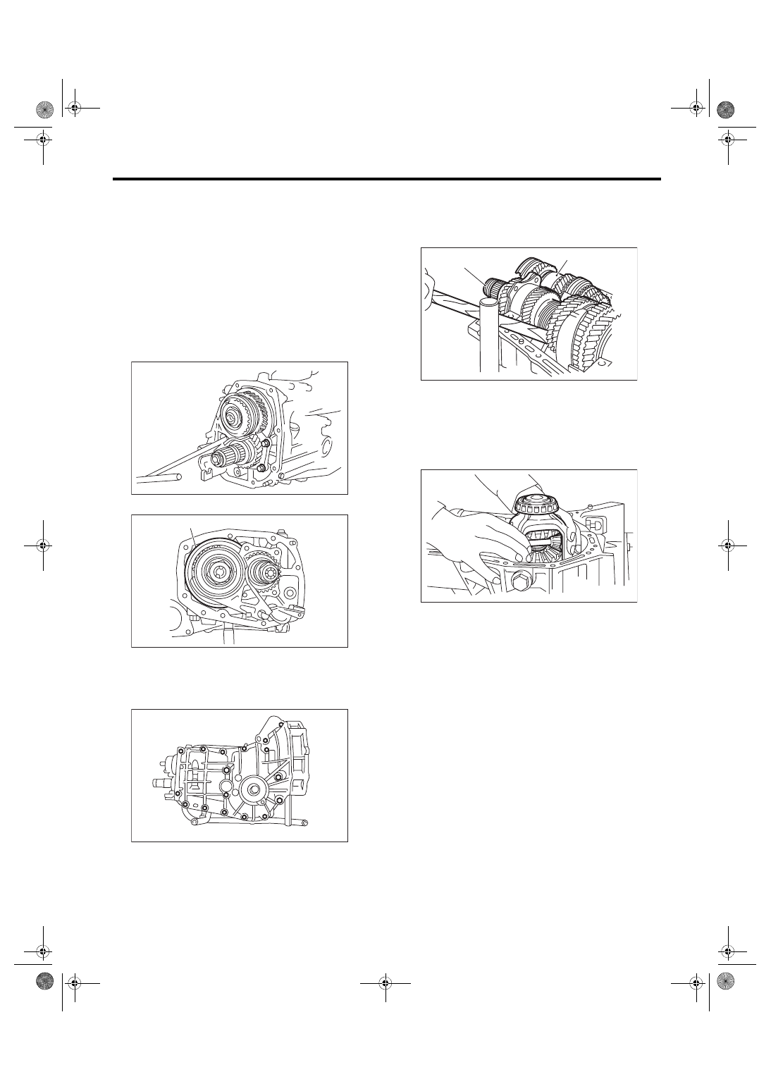
4) Remove the bearing mounting bolt.
5) Remove the main shaft rear plate.
6) Remove the bolts and nuts, and separate the
transmission case into the right and left case.
7) Remove the drive pinion shaft assembly from
the left side of the transmission case.
NOTE:
Use a hammer handle, etc. to remove if too tight.
8) Remove the main shaft assembly for single-
range.
9) Remove the front differential assembly.
10) Remove the differential side retainers and
bearing outer races on the left and right side. <Ref.
to 5MT-69, REMOVAL, Front Differential Assem-
bly.>
NOTE:
Do not confuse the right and left roller bearing outer
races.
11) Remove the reverse idler gear. <Ref. to 5MT-
77, REMOVAL, Reverse Idler Gear.>
12) Remove the shifter fork and rod. <Ref. to 5MT-
79, REMOVAL, Shifter Fork and Rod.>
(A) Main shaft rear plate
MT-01514
(A)
MT-01515
MT-00160
(A) Main shaft ASSY for single-range
(B) Drive pinion shaft ASSY
MT-00161
( A )
( B )
MT-00162
5MT-50
Transmission Case
MANUAL TRANSMISSION AND DIFFERENTIAL
B: INSTALLATION
1) Wipe off grease, oil and dust on the mating sur-
faces of transmission cases with cleaning solvent.
2) Install the shifter fork and rod. <Ref. to 5MT-80,
INSTALLATION, Shifter Fork and Rod.>?
3) Install the reverse idler gear. <Ref. to 5MT-77,
INSTALLATION, Reverse Idler Gear.>
4) Select the drive pinion shim. <Ref. to 5MT-58,
INSTALLATION, Drive Pinion Shaft Assembly.>
5) Install the differential side retainer, from which
the bearing outer race and O-ring have already
been removed, to the transmission case LH side.
6) Install the front differential assembly.
7) Install the main shaft assembly for single-range.
Align the transmission case knock pin into the
knock pin hole of the needle bearing.
8) Install the selected drive pinion shims and drive
pinion shaft assembly.
NOTE:
Align the roller bearing knock pin hole to the trans-
mission case knock pin.
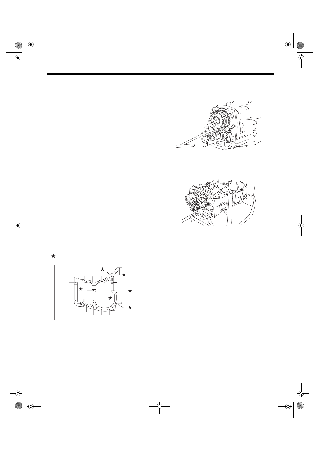
9) Tighten the left and right side of the transmission
case with the17 mounting bolts.
NOTE:
• Insert bolts (11) and (16) from the LH side of the
transmission case.
• Match the cases together so that the drive pinion
shims are not caught between the cases.
Tightening torque:
8 mm bolt
25 N·m (2.5 kgf-m, 18.4 ft-lb)
10 mm bolt
39 N·m (4.0 kgf-m, 28.8 ft-lb)
10) Install the bearing outer race to the RH side of
the transmission case.
11) Tighten the bearing mounting bolts.
Tightening torque:
30 N·m (3.1 kgf-m, 22.1 ft-lb)
12) Adjust the backlash of the hypoid gear and the
preload of the roller bearing.
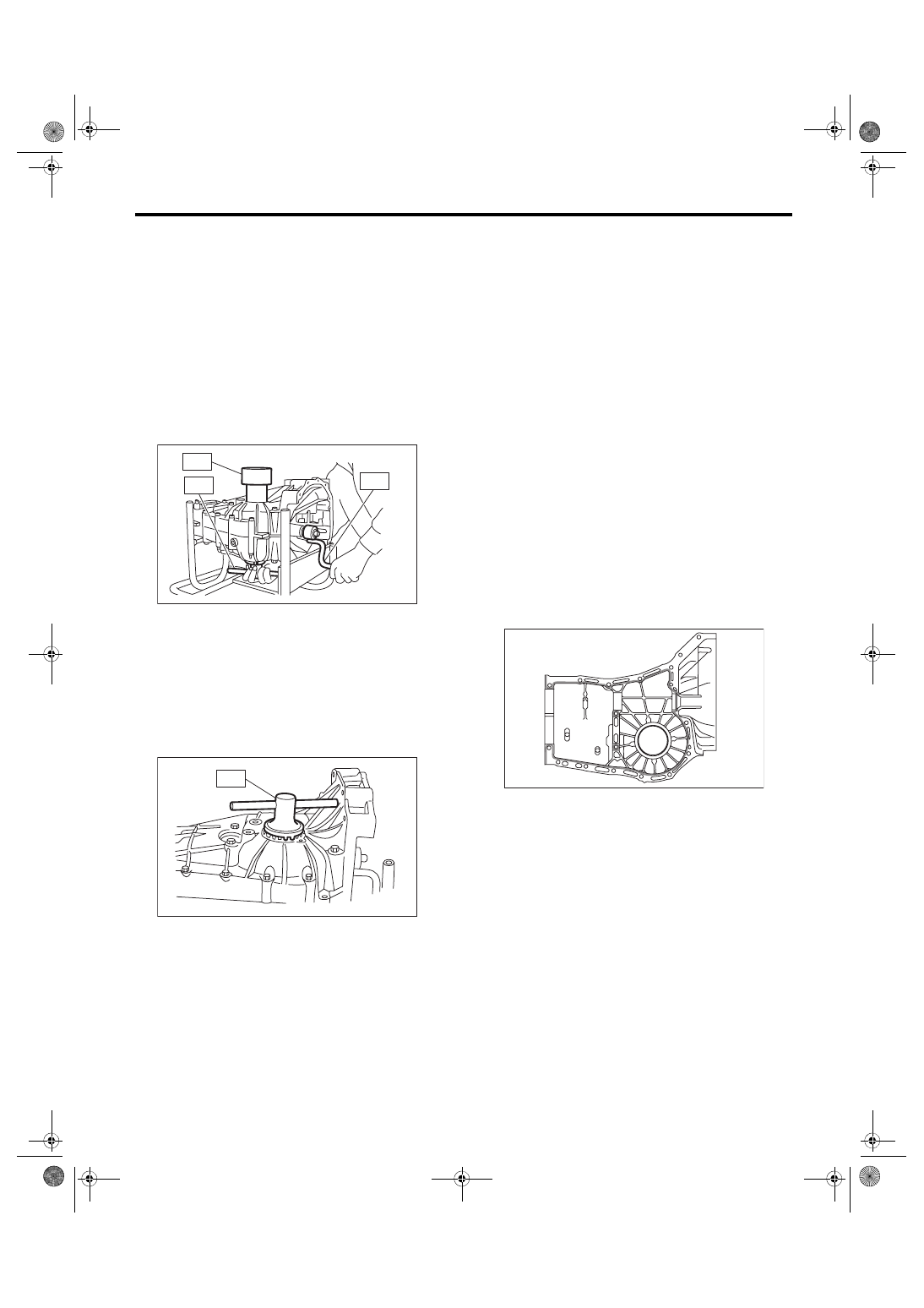
(1) Attach the ST on drive pinion assembly.
ST 498427100
STOPPER
(2) Place the transmission with the LH side of
case facing downward, and put ST1 on the
bearing outer race.
(9)
(7)
(5)
(16)
(17)
(11)
(3)
(4)
(2)
(1)
(12)
(8)
(6)
(10)
(14)
(15)
(13)
MT-00178
MT-01514
ST
MT-01516
5MT-51
Transmission Case
MANUAL TRANSMISSION AND DIFFERENTIAL
(3) Screw the retainer assembly from the bot-
tom into left case using ST2. Fit the ST3 on
transmission main shaft. Shift the gear into 4th
or 5th, and turn the shaft several times. Screw
in the retainer while rotating the ST3 until a
slight resistance is felt on ST2.
This is the contact point of the hypoid gear and
the drive pinion shaft. Repeat the above se-
quence several times to ensure the contact
point.
ST1 399780104
WEIGHT
ST2 18630AA010 WRENCH COMPL RETAIN-
ER
ST3 499927100
HANDLE
(4) Remove the WEIGHT, and screw in the side
retainer without the O-ring into the RH side of
the transmission case, and stop at the point
where a slight resistance is felt.
NOTE:
In this condition, the backlash between hypoid gear
and drive pinion shaft is zero.
ST 18630AA010 WRENCH COMPL RETAIN-
ER
(5) Loosen the side retainer on the LH side of
the transmission case by 3 notches, and turn
the side retainer on the RH side of the transmis-
sion case by the same notches in order to apply
backlash.
(6) Screw in the side retainer of the RH side of
the transmission case additionally by 1 notch in
order to apply preload on taper roller bearing.
(7) Tighten temporarily both the upper and low-
er lock plates, and put marks on both the side
retainer and lock plate for later readjustment.
NOTE:
If it is hard to install the lock plates, reverse the
sides and install them.
(8) Turn the transmission main shaft several
times while tapping around the retainer lightly
with plastic hammer.
13) Inspect and adjust backlash and tooth contact
of the hypoid gear. <Ref. to 5MT-73, INSPECTION,
14) Separate the transmission case into left and
right parts. <Ref. to 5MT-49, REMOVAL, Transmis-
15) Select a main shaft rear plate. <Ref. to 5MT-57,
ADJUSTMENT, Main Shaft Assembly for Single-
16) Check each shifter fork. <Ref. to 5MT-81, IN-
SPECTION, Shifter Fork and Rod.>
17) Apply liquid gasket, then join the right side and
left side of the case together.
Liquid gasket:
THREE BOND 1215 (Part No. 004403007) or
equivalent
MT-02407
ST3
ST2
ST1
MT-00176
ST
MT-02616
5MT-52
Transmission Case
MANUAL TRANSMISSION AND DIFFERENTIAL
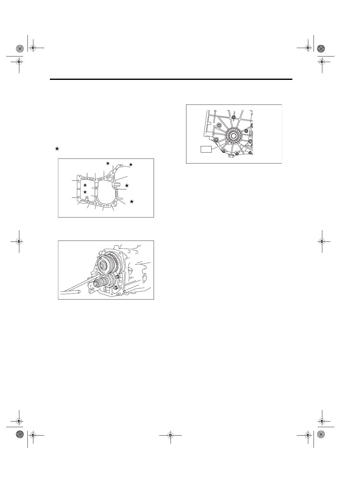
18) With brackets and clips as shown in the figure,
tighten the seventeen bolts.
NOTE:
• Insert bolts (11) and (16) from the LH side of the
transmission case.
• Match the cases together so that the drive pinion
shims are not caught between the cases.
Tightening torque:
8 mm bolt
25 N·m (2.5 kgf-m, 18.4 ft-lb)
10 mm bolt
39 N·m (4.0 kgf-m, 28.8 ft-lb)
19) Tighten the bearing mounting bolts.
Tightening torque:
30 N·m (3.1 kgf-m, 22.1 ft-lb)
20) Remove the lock plate. Then loosen the retain-
er until the O-ring groove appears. Fit the O-ring
into the groove and tighten the retainer into the po-
sition where it was not loosened.
NOTE:
• When loosening the retainer, record the number
of the turns made.
• Perform this for both left and right side retainers.
• Use new O-rings.
21) Install the lock plate.
Tightening torque:
T: 25 N·m (2.5 kgf-m, 18.4 ft-lb)
22) Install the transfer case together with the exten-
sion case assembly. <Ref. to 5MT-35, INSTALLA-
TION, Transfer Case and Extension Case
23) Install the clutch release lever and bearing.
<Ref. to CL-15, INSTALLATION, Release Bearing
24) Install the manual transmission assembly to the
vehicle. <Ref. to 5MT-26, INSTALLATION, Manual
C: INSPECTION
Check the transmission case for cracks, damage,
or oil leaks.
MT-00172
(9)
(7)
(5)
(1)
(2)
(16)
(17)
(11)
(3)
(4)
(12)
(8)
(6)
(10)
(14)
(15)
(13)
MT-01514
MT-00177
T
Нет комментариевНе стесняйтесь поделиться с нами вашим ценным мнением.
Текст