Subaru Impreza 3 / Impreza WRX / Impreza WRX STI. Service manual — part 700
GW-33
Rear Window Defogger System
GLASS/WINDOWS/MIRRORS
16.Rear Window Defogger Sys-
tem
A: WIRING DIAGRAM
Refer to “Rear Defogger System” in the wiring dia-
gram. <Ref. to WI-135, WIRING DIAGRAM, Rear
B: INSPECTION
1. SYSTEM INSPECTION
NOTE:
Rear window defogger system can be customized
on the Subaru Select Monitor, when the body inte-
grated unit customize setting {A/C ECM setting} is
“support”.
2. CHECK WITH SUBARU SELECT MONI-
TOR
CAUTION:
Check whether the “Rr defogger op. mode” set-
ting is in initial setting or customize setting be-
fore performing inspection.
1) Check the input signal when the rear window de-
fogger switch is operated using Subaru Select
Monitor.
(1) Prepare the Subaru Select Monitor. <Ref. to
GW-7, PREPARATION TOOL, General De-
(2) Turn the ignition switch to ON (engine OFF)
and run the “PC application for Subaru Select
Monitor”.
(3) On «System Selection Menu» display, se-
lect {Integ. unit mode}.
(4) Select the {Rr defogger output} on {Current
Data Display & Save}.
(5) Check the displayed data (ON/OFF) by op-
erating the rear window defogger switch.
2) Check the operation with rear window defogger
switch ON.
• When customize setting is set as “Continuous”, it
is normal if the 15-minute operation and 2-minute
stop repeats.
• When customize setting is “Normal”, it is normal
if the operation lasts for 15 minutes and then turns
OFF.
3) When the operation in 2) above fails, replace the
body integrated unit.
3. HEAT WIRE INSPECTION
CAUTION:
When wiping off the stain on glass with cloth,
use a dry and soft cloth and move it in the direc-
tion of the heat wire extension to avoid damage
to the heat wire.
1) Prepare the following checking items.
• Liquid crystal thermograph sheet (approximate
size: 300 × 300 mm (11.8 × 11.8 in) and thermal
temperature: 35 — 40°C (95 — 104°F))
• Aluminum foil
2) Turn the ignition switch to ON.
3) Turn the defogger switch to ON.
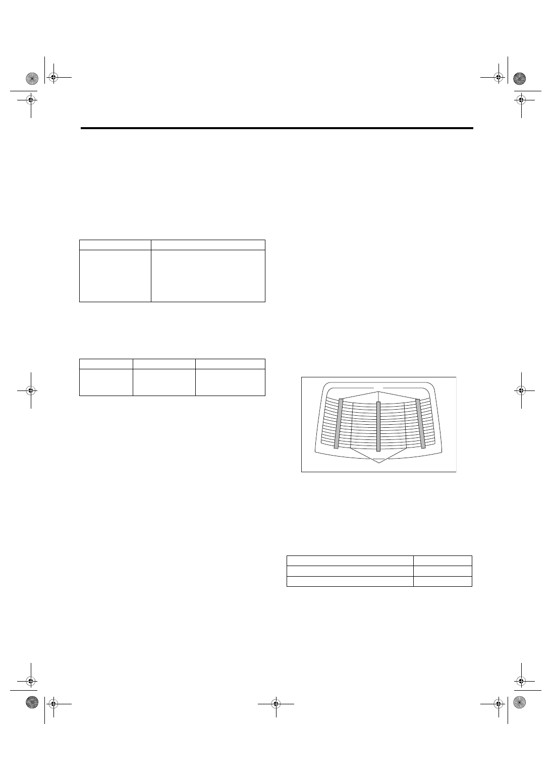
4) Push the liquid crystal thermograph sheet from
the outside of the rear glass.
NOTE:
Use the liquid crystal thermograph sheet every
range it is separated with the separate line.
5) Determine the faulty heat wire by checking the
color of the liquid crystal thermograph sheet.
NOTE:
• Check from the inside of the glass if the liquid
crystal thermograph sheet does not change.
• The time for the color change may differ depends
on the surface temperature of the glass.
Symptom
Repair order
Rear window defog-
ger does not operate.
1. Check the fuse.
2. Check the rear defogger relay.
3. Check the rear defogger switch.
4. Check the heat wire.
5. Check the wiring harness.
6. Check body integrated unit.
System name
Initial setting
Customize setting
Rr defogger op.
mode
OFF after 15 min.
Repeat 15 min. oper-
ation and 2 min.
stop.
(A) Liquid crystal thermograph sheet
(B) Separate line
Liquid crystal thermograph sheet
Criteria
Change occurred (red → blue)
Normal
No change (black)
Open
(A)
(B)
GW-00756
GW-34
Rear Window Defogger System
GLASS/WINDOWS/MIRRORS
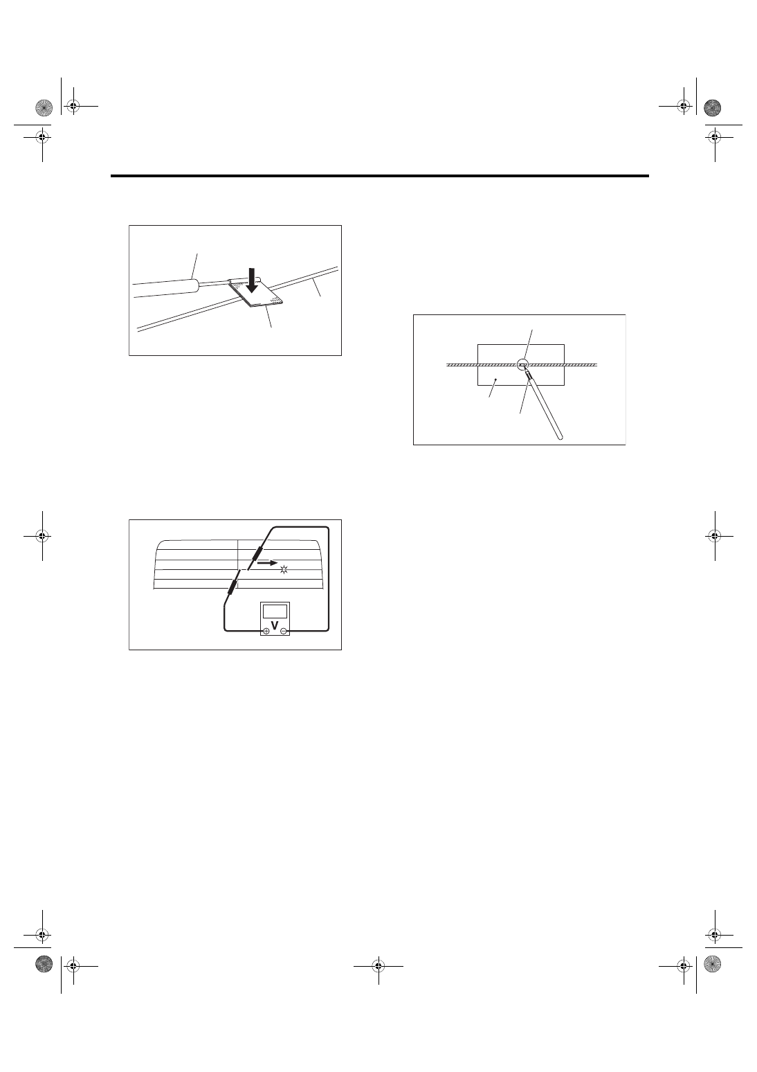
6) Wrap a piece of aluminum foil around the tip of
tester probe and press it against the heat wire with
your finger.
7) To both ends of the section that has been found
to include an open in the step 5), apply the tester
positive (+) probe and the negative (–) probe.
8) Move the tester probe on the negative (–) side
slowly along the heat wire. If voltage changes from
zero to several volts during movement of tester
probe, heat wire is open at the voltage change
point.
9) Repair the heat wire that determines the place of
the open circuit. <Ref. to GW-34, REPAIR, Rear
C: REPAIR
1) Clean the broken portion with alcohol or white
gasoline.
2) Mask both side of wire with masking tape.
3) Apply the conductive silver composition to the
broken portion.
Conductive silver composition:
Permatex’s
QUICK GRID
4) Dry using a dryer after applying the composition.
5) After repair, check the wire.
(A) Tester probe
(B) Aluminum foil
(C) Heat wire
ET-00007
(B)
(C)
(A)
ET-00333
(1) Broken portion
(2) Masking tape
(3) Broken wire
(4) Conductive silver composition
GW-00078
(2)
(3)
(4)
(1)
GW-35
Rear Quarter Glass
GLASS/WINDOWS/MIRRORS
17.Rear Quarter Glass
A: REMOVAL
1) Disconnect the ground cable from battery.
2) Remove the rear quarter trim.
• 5 door model: <Ref. to EI-60, 5 DOOR MODEL,
• 4 door model: <Ref. to EI-61, 4 DOOR MODEL,
3) Remove the rear quarter glass in the same pro-
cedure as for windshield glass. <Ref. to GW-23,
B: INSTALLATION
1. 5 DOOR MODEL
1) Mount the fastener on the vehicle body.
2) Apply the primer to the glass and body sides in
the same procedure as for windshield glass. <Ref.
to GW-24, INSTALLATION, Windshield Glass.>
CAUTION:
Do not allow the primer to come in contact with
the molding during the application of the prim-
er.
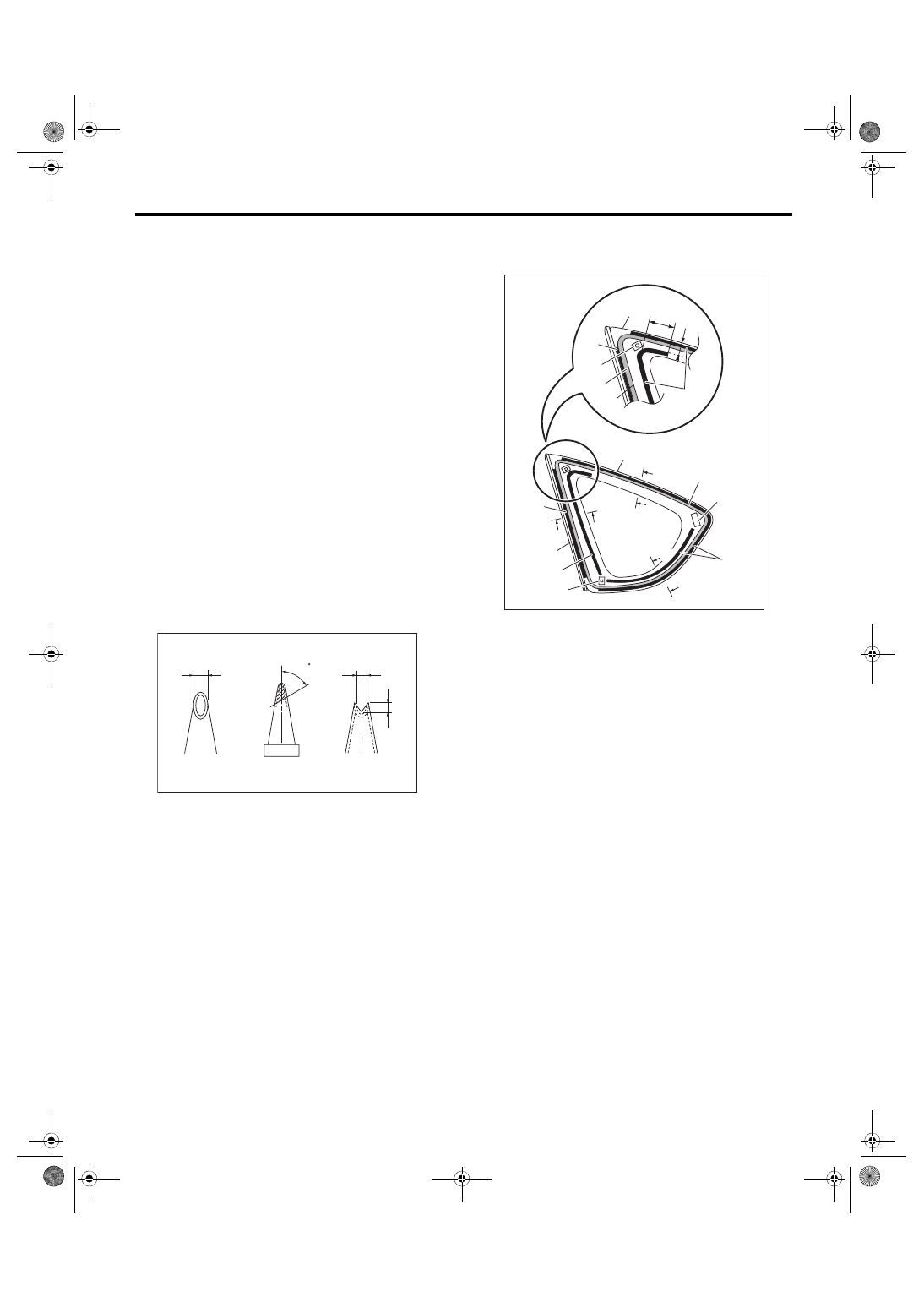
3) Fabricate the cartridge nozzle tip as shown and
set the sealant gun with the adhesive.
4) Apply adhesive with the dam rubber installed in
the same procedure as for windshield glass. <Ref.
to GW-24, INSTALLATION, Windshield Glass.>
(1) 10 mm (0.39 in)
(2) 8 mm (0.31 in)
GW-00494
(1)
(2)
(2)
60
(1) Glass
(2) Adhesive
(3) Dam rubber
(4) Molding
(5) Fastener
(6) Clip
(7) 66 mm (2.60 in)
(8) 17 mm (0.61 in)
GW-01368
(2)
(3)
(1)
(4)
A
A
C
A
B
(5)
C
A
B
(3)
(6)
(3)
(4)
(1)
(7)
(8)
(2)
(6)
(3)
(3)
GW-36
Rear Quarter Glass
GLASS/WINDOWS/MIRRORS
5) Insert the glass locating pin into the hole on side
panel and push on the area around the locating pin
to secure it.
Then push lightly all around the locating pin to seal
it.
6) After completion of all work, allow the vehicle to
stand for about 24 hours.
NOTE:
• When door is opened/closed after glass is bond-
ed, always lower the door glass first, and then
open/close it carefully.
• Move the vehicle slowly.
• For minimum drying time and vehicle standing
time before driving after bonding, follow instruc-
tions or instruction manual from the adhesive man-
ufacturer.
7) After curing of adhesive, pour the water on exter-
nal surface of vehicle to check that there are no wa-
ter leaks.
NOTE:
When a vehicle is returned to the user, tell him or
her that the vehicle should not be subjected to
heavy impact for at least three days.
8) Install the rear quarter trim. <Ref. to EI-61, IN-
STALLATION, Rear Quarter Trim.>
2. 4 DOOR MODEL
1) Mount the fastener on the vehicle body.
2) Apply the primer to the glass and body sides in
the same procedure as for windshield glass. <Ref.
to GW-24, INSTALLATION, Windshield Glass.>
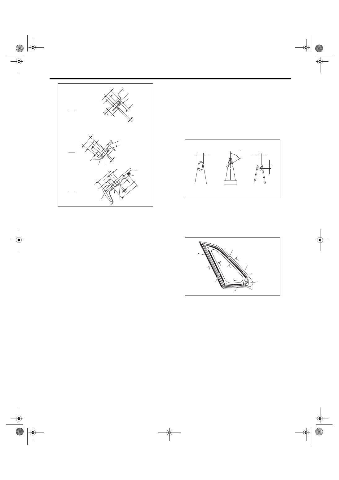
3) Fabricate the cartridge nozzle tip as shown and
set the sealant gun with the adhesive.
4) Apply adhesive with the dam rubber installed in
the same procedure as for windshield glass. <Ref.
to GW-24, INSTALLATION, Windshield Glass.>
A Upper end
B Lower end
C Front end
(1) Glass
(2) Adhesive
(3) Molding
(4) Dam rubber
B
A
C
(4)
9 mm (0.35 in)2 mm
(0.08 in)
8 mm (0.31 in)
12 mm (0.47 in)
(2)
(1)
GW-01369
4 mm
(0.16 in)
9 mm (0.35 in)
2 mm
(0.08 in)
8 mm
(0.31 in)
13 mm
(0.51 in)
(2)
(1)
(4)
18 mm
(0.71 in)
5 mm
(0.2 in)
(4)
9 mm (0.35 in)
2 mm
(0.08 in)
(3)
8 mm (0.31 in) (1)
24.2 mm
(0.95 in)
(2)
26.7 mm
(1.05 in)
(4)
(4)
1.5 mm
(0.06 in)
(1) 10 mm (0.39 in)
(2) 8 mm (0.31 in)
(1) Glass
(2) Adhesive
(3) Dam rubber
(4) Molding
(5) Fastener
GW-00494
(1)
(2)
(2)
60
GW-00807
(4)
C
C
B
B
A
A
(2)
(5)
(1)
(3)
(3)
(3)
Нет комментариевНе стесняйтесь поделиться с нами вашим ценным мнением.
Текст