Subaru Impreza 3 / Impreza WRX / Impreza WRX STI. Service manual — part 701
GW-37
Rear Quarter Glass
GLASS/WINDOWS/MIRRORS
5) Insert the glass locating pin into the hole on side
panel and push on the area around the locating pin
to secure it. Then push lightly all around the locat-
ing pin to seal it.
6) After completion of all work, allow the vehicle to
stand for about 24 hours.
NOTE:
• When door is opened/closed after glass is bond-
ed, always lower the door glass first, and then
open/close it carefully.
• Move the vehicle slowly.
• For minimum drying time and vehicle standing
time before driving after bonding, follow instruc-
tions or instruction manual from the adhesive man-
ufacturer.
7) After curing of adhesive, pour the water on exter-
nal surface of vehicle to check that there are no wa-
ter leaks.
NOTE:
When a vehicle is returned to the user, tell him or
her that the vehicle should not be subjected to
heavy impact for at least three days.
8) Install the rear quarter trim. <Ref. to EI-61, IN-
STALLATION, Rear Quarter Trim.>
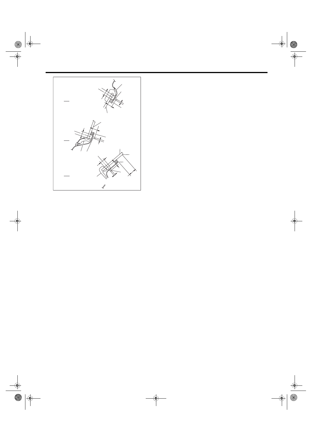
A Upper end
B Lower end
C Front end
(1) Glass
(2) Molding
(3) Adhesive
(4) Dam rubber
(5) Ceramic line edge
B
A
C
(1)
GW-00767
(2)
8 mm
(3)
2 mm (0.08 in)
8 mm
(3)
(1)
(4)
(4)
8 mm
(3)
(1)
(2)
(2)
(4)
(5)
(0.31 in)
(0.31 in)
(0.31 in)
13 mm
(0.51 in)
9 mm
(0.35 in)
9 mm (0.35 in)
9 mm (0.35 in)
2 mm (0.08 in)
2 mm
(0.08 in)
GW-38
Rearview Mirror
GLASS/WINDOWS/MIRRORS
18.Rearview Mirror
A: REMOVAL
CAUTION:
• Never reuse the spring. When the rearview
mirror assembly is removed from the mirror
base, fixed force will decline and the rearview
mirror assembly may come off.
• Be careful not to damage the mirror surface
and windshield glass.
NOTE:
Never reuse the spring. Prepare a new spring be-
fore removal.
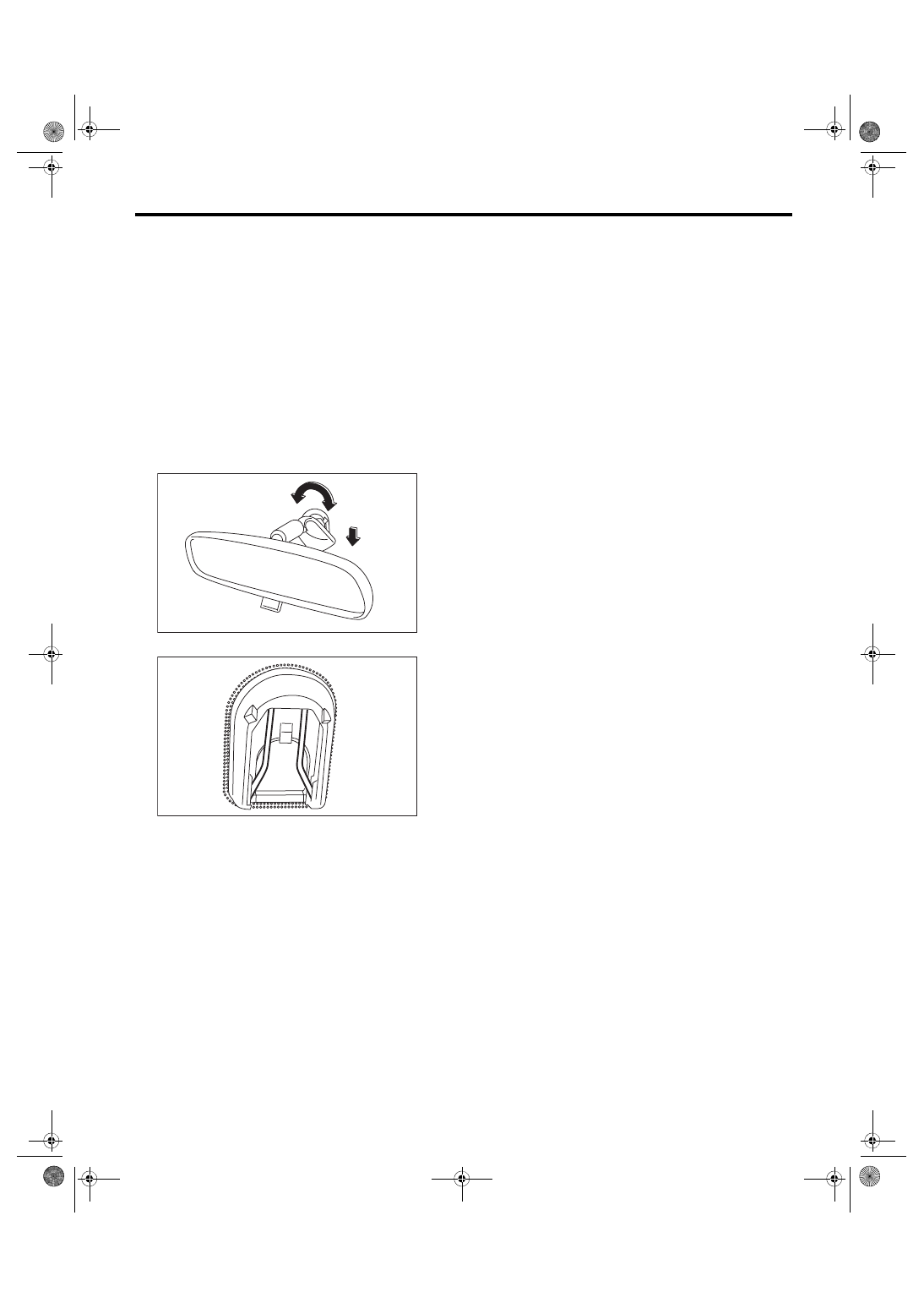
1) Turn the mirror base 90° clockwise or counter-
clockwise to remove it.
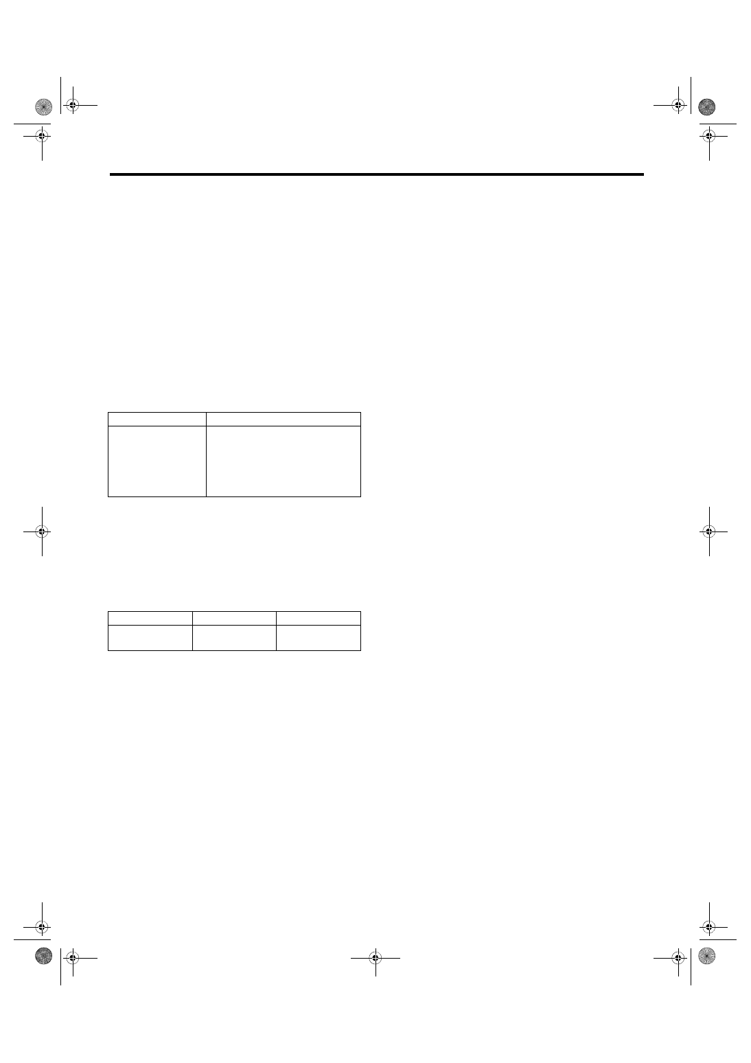
2) Remove the spring from the mirror base.
3) If the mirror base is damaged, replace the wind-
shield glass.
B: INSTALLATION
Install each part in the reverse order of removal.
C: INSPECTION
Check the mirror, mirror base and spring for dam-
age, and replace if defective.
GW-00046
GW-00047
GW-39
Wiper Deicer System
GLASS/WINDOWS/MIRRORS
19.Wiper Deicer System
A: WIRING DIAGRAM
Refer to “Wiper Deicer System” in the wiring dia-
gram. <Ref. to WI-112, WIRING DIAGRAM, Wiper
B: INSPECTION
1. SYSTEM INSPECTION
NOTE:
• The wiper deicer does not operate when the am-
bient temperature becomes 5°C (41°F) or more.
• The wiper deicer operates with the rear window
defogger at the same time.
• It is possible to perform a forced operation if you
keep holding the rear window defogger switch for 3
seconds or more.
NOTE:
• Wiper deicer system can be customized using
the Subaru Select Monitor, when the customize
setting {A/C ECM setting} of the body integrated
unit is set to With.
• Set the system using the Rr Defogger op. mode,
and setting will be the same as rear defogger sys-
tem setting.
*: When one of the following conditions occurs, continuous
operation is suspended and turned off after 15 minutes.
• Ambient temperature at 5°C (41°F) or more continues for
10 seconds.
• Malfunction occurs on ambient sensor.
• Vehicle speed of 15 km/h (9 MPH) or less continues 15
minutes (OFF when conditions are met)
• Malfunction occurs in CAN communication.
• Battery voltage remains at 10 V or less for 30 seconds.
• SI-DRIVE [I] mode driving continues for 10 seconds.
2. CHECK WITH SUBARU SELECT MONI-
TOR
CAUTION:
Before performing the inspection, check the
following settings.
• Wiper deicer setting → “support”. If “no sup-
port”, set to “support” using customize setting.
• “Rr defogger op. mode” setting → Initial set-
ting or customize setting
1) Check the input signal when the rear window de-
fogger switch is operated using Subaru Select
Monitor.
(1) Prepare the Subaru Select Monitor. <Ref. to
GW-7, PREPARATION TOOL, General De-
(2) Turn the ignition switch to ON (engine OFF)
and run the “PC application for Subaru Select
Monitor”.
(3) On «System Selection Menu» display, se-
lect {Integ. unit mode}.
(4) Select the {wiper deicer output} on {Current
Data Display & Save}.
(5) Check the displayed data (ON/OFF) by op-
erating the rear window defogger switch.
2) Check the operation with rear window defogger
switch ON.
• When customize setting is “Continuous”, it is nor-
mal if the operation lasts without any termination
conditions.
• When customize setting is “Normal”, it is normal
if the operation lasts for 15 minutes and then turns
OFF.
3) When the operation in 2) above fails, replace the
body integrated unit.
3. HEAT WIRE INSPECTION
For operation procedures, refer to “HEAT WIRE IN-
SPECTION” of “Rear Window Defogger System”.
<Ref. to GW-33, HEAT WIRE INSPECTION, IN-
SPECTION, Rear Window Defogger System.>
NOTE:
Heat wire inspection needs removing/installing pro-
cedure of instrument panel assembly.
C: REPAIR
For operation procedures, refer to “REPAIR” of
“Rear Window Defogger System”. <Ref. to GW-34,
REPAIR, Rear Window Defogger System.>
NOTE:
Heat wire repair needs removing/installing proce-
dure of instrument panel assembly.
Symptoms
Inspection order
Wiper deicer does not
operate.
1. Check the fuse.
2. Check the wiper deicer relay.
3. Check the rear defogger switch.
4. Check the heat wire.
5. Check the wiring harness.
6. Check body integrated unit.
System name
Initial setting
Customize setting
Rr defogger op.
mode
OFF after 15 min.
Continuous opera-
tion*
GW-40
Wiper Deicer System
GLASS/WINDOWS/MIRRORS
Нет комментариевНе стесняйтесь поделиться с нами вашим ценным мнением.
Текст