Subaru Impreza 3 / Impreza WRX / Impreza WRX STI. Service manual — part 128
FU(w/o STI)-39
Knock Sensor
FUEL INJECTION (FUEL SYSTEMS)
7. Knock Sensor
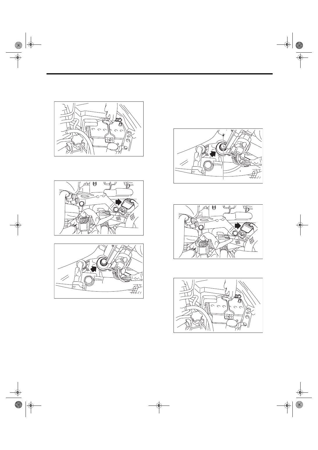
A: REMOVAL
1) Disconnect the ground cable from battery.
2) Remove the intercooler. <Ref. to IN(w/o STI)-12,
3) Disconnect the connector from the knock sen-
sor.
4) Remove the knock sensor from cylinder block.
B: INSTALLATION
1) Install the knock sensor to the cylinder block.
NOTE:
The portion of the knock sensor cord that is pulled
out must be positioned at a 60° angle relative to the
engine rear.
Tightening torque:
24 N·m (2.4 kgf-m, 17.7 ft-lb)
2) Connect the connector to the knock sensor.
3) Install the intercooler. <Ref. to IN(w/o STI)-12,
4) Connect the battery ground terminal.
IN-00203
FU-05716
FU-05750
(A) Front side of vehicle
FU-05751
(A)
60
FU-05716
IN-00203
FU(w/o STI)-40
Knock Sensor
FUEL INJECTION (FUEL SYSTEMS)
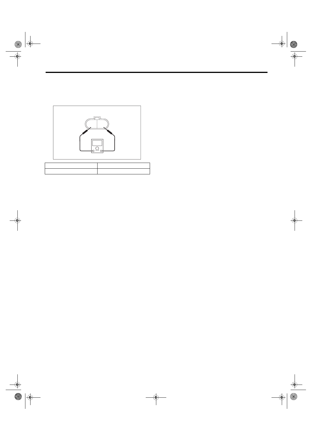
C: INSPECTION
1) Check that the knock sensor has no deforma-
tion, cracks or other damages.
2) Measure the resistance between knock sensor
terminals.
Terminal No.
Standard
1 and 2
560±28 kΩ
2 1
EC-02426
FU(w/o STI)-41
Throttle Position Sensor
FUEL INJECTION (FUEL SYSTEMS)
8. Throttle Position Sensor
A: SPECIFICATION
Throttle body is a non-disassembled part, so do not
remove the throttle position sensor from throttle
body.
Refer to “Throttle Body” for removal and installation
procedure. <Ref. to FU(w/o STI)-15, REMOVAL,
FU(w/o STI)-42
Mass Air Flow and Intake Air Temperature Sensor
FUEL INJECTION (FUEL SYSTEMS)
9. Mass Air Flow and Intake Air
Temperature Sensor
A: REMOVAL
1) Disconnect the ground cable from battery.
2) Disconnect the connector (A) from the mass air
flow and intake air temperature sensor, and re-
move the mass air flow and intake air temperature
sensor.
B: INSTALLATION
Install in the reverse order of removal.
Tightening torque:
1 N·m (0.1 kgf-m, 0.7 ft-lb)
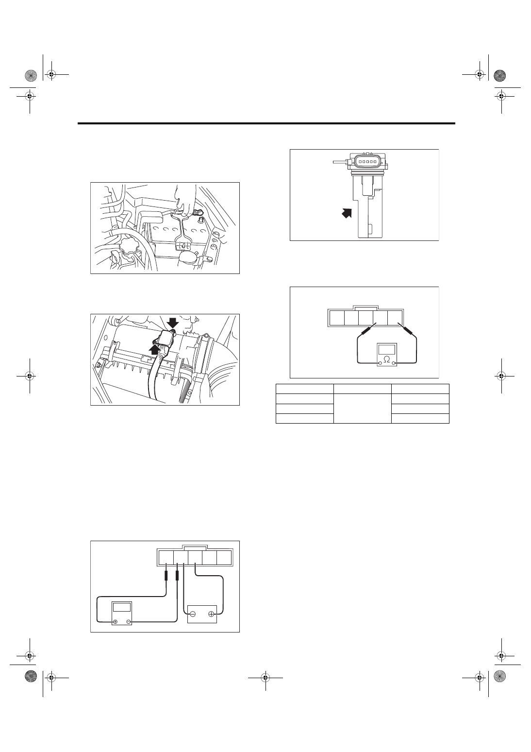
C: INSPECTION
1. CHECK THE MASS AIR FLOW SENSOR
UNIT
1) Connect the battery positive terminal to terminal
No. 3 and the battery ground terminal to terminal
No. 4, the circuit tester positive terminal to terminal
No. 5 and the circuit tester ground terminal to termi-
nal No. 4.
2) Check the voltage changes when air is blown to
the mass air flow sensor unit in arrow direction.
2. CHECK THE INTAKE AIR TEMPERA-
TURE SENSOR UNIT
Measure the resistance between intake air temper-
ature sensor terminals.
3. OTHER INSPECTIONS
1) Check that the mass air flow and intake air tem-
perature sensor has no deformation, cracks or oth-
er damages.
2) Check that the mass air flow and intake air tem-
perature sensor has no dirt.
IN-00203
FU-05798
(A)
5 4 3 2 1
FU-04062
V
Temperature
Terminal No.
Standard
–20°C (–4°F)
1 and 2
16.0±2.4 kΩ
20°C (68°F)
2.45±0.24 kΩ
60°C (140°F)
0.580±0.087 kΩ
FU-04063
FU-04064
5 4 3 2 1
Нет комментариевНе стесняйтесь поделиться с нами вашим ценным мнением.
Текст