Subaru Impreza 3 / Impreza WRX / Impreza WRX STI. Service manual — part 129
FU(w/o STI)-43
Manifold Absolute Pressure Sensor
FUEL INJECTION (FUEL SYSTEMS)
10.Manifold Absolute Pressure
Sensor
A: REMOVAL
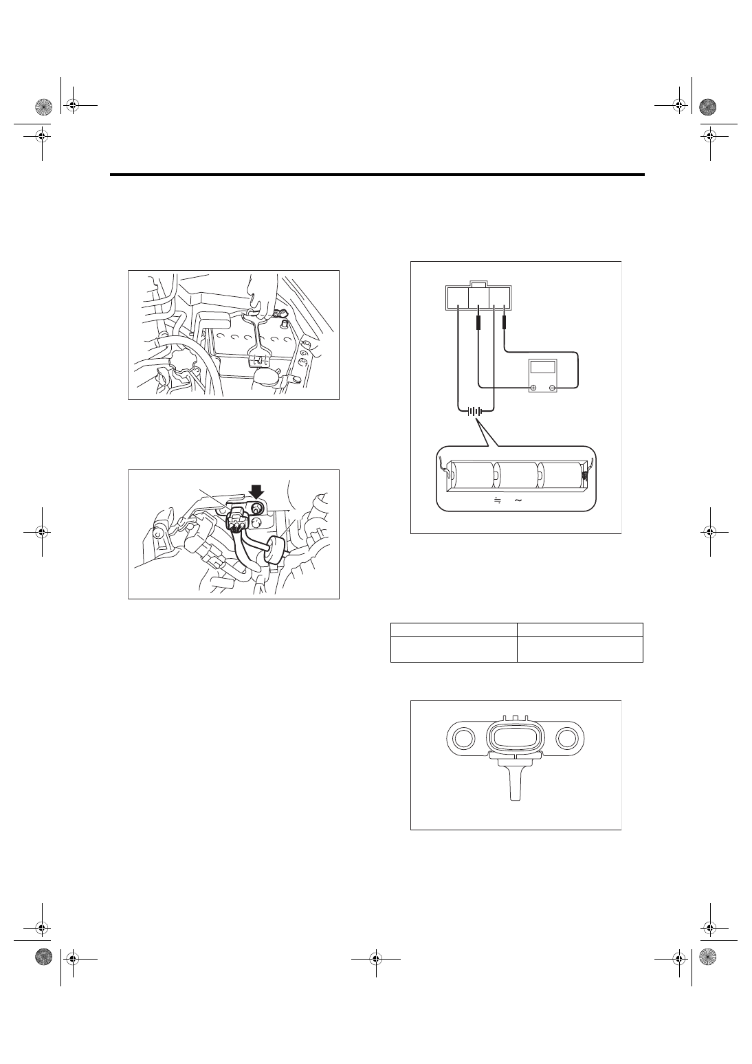
1) Remove the collector cover.
2) Disconnect the ground cable from battery.
3) Disconnect the connector (A) from manifold ab-
solute pressure sensor, and remove the filter as-
sembly (B) from intake manifold.
4) Remove the manifold absolute pressure sensor
from the solenoid valve bracket.
B: INSTALLATION
Install in the reverse order of removal.
Tightening torque:
6.4 N·m (0.7 kgf-m, 4.7 ft-lb)
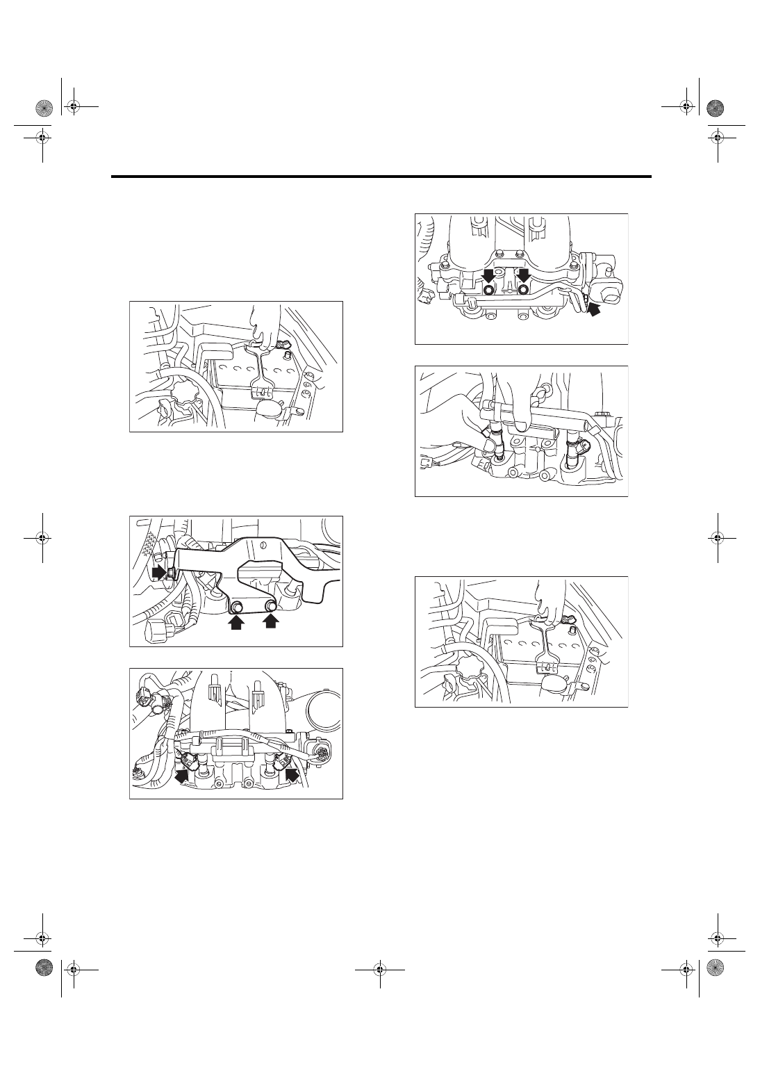
C: INSPECTION
1) Check that the manifold absolute pressure sen-
sor has no deformation, cracks or other damages.
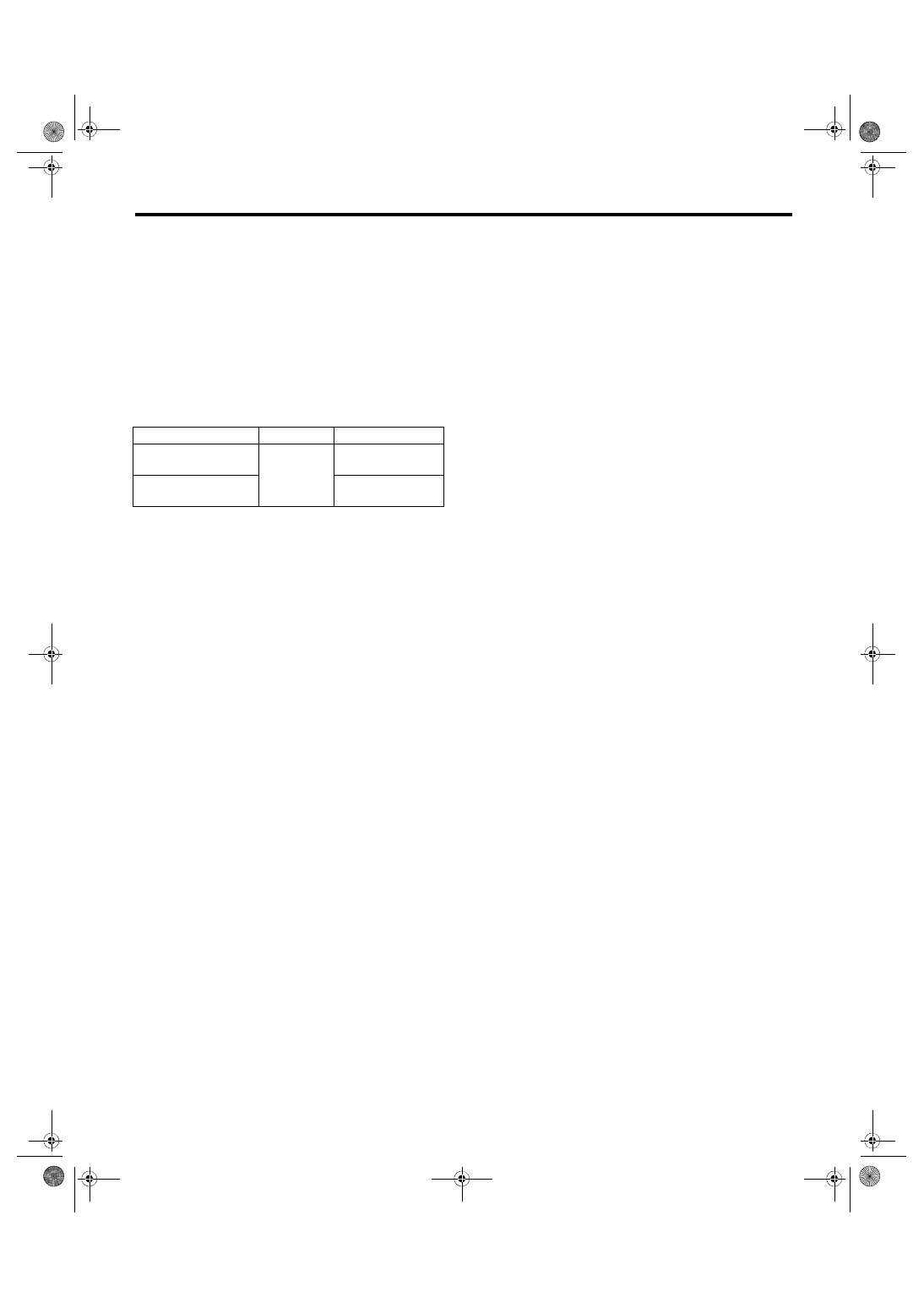
2) Connect dry-cell battery positive terminal to ter-
minal No. 3 and dry-cell battery ground terminal to
terminal No. 1, circuit tester positive terminal to ter-
minal No. 2 and the circuit tester negative terminal
to terminal No. 1.
NOTE:
• Use new dry-cell batteries.
• Using circuit tester, check the voltage of a single
dry-cell battery is 1.6 V or more. And also check the
voltage of three batteries in series is between 4.8 V
and 5.2 V.
3) Check the voltage at a normal atmospheric pres-
sure.
NOTE:
The atmospheric pressure at higher altitude is low-
er than normal. Therefore, the voltage is lower than
the standard value.
4) Connect the Mighty Vac to the pressure port (A)
of manifold absolute pressure sensor.
IN-00203
(A)
FU-05757
(B)
Terminal No.
Standard
2 (+) and 1 (–)
Approx. 2.2 V
(when 25°C (77°F))
FU-04486
3 2 1
V
1.5V
1.5V
1.5V
4.8 5.2V
FU-04487
(A)
FU(w/o STI)-44
Manifold Absolute Pressure Sensor
FUEL INJECTION (FUEL SYSTEMS)
5) Check the voltage when generating vacuum and
positive pressure using Mighty Vac.
CAUTION:
Do not apply vacuum of less than –88 — 200
kPa (–0.9 — 2.04 kgf/cm
2
, –12.8 — 29.0 psi). Do-
ing so may damage the manifold absolute pres-
sure sensor.
NOTE:
When vacuum occurs at the pressure port of man-
ifold absolute pressure sensor, the voltage will drop
from the value as in step 3). When positive pres-
sure occurs, on the other hand, the voltage will rise.
Pressure
Terminal No.
Standard
–88 kPa (–0.9 kgf/cm
2
,
–12.8 psi)
2 (+) and
1 (–)
Approx. 1.0 V
(when 25°C (77°F))
152 kPa (1.55 kgf/cm
2
,
22.0 psi)
Approx. 4.5 V
(when 25°C (77°F))
FU(w/o STI)-45
Fuel Injector
FUEL INJECTION (FUEL SYSTEMS)
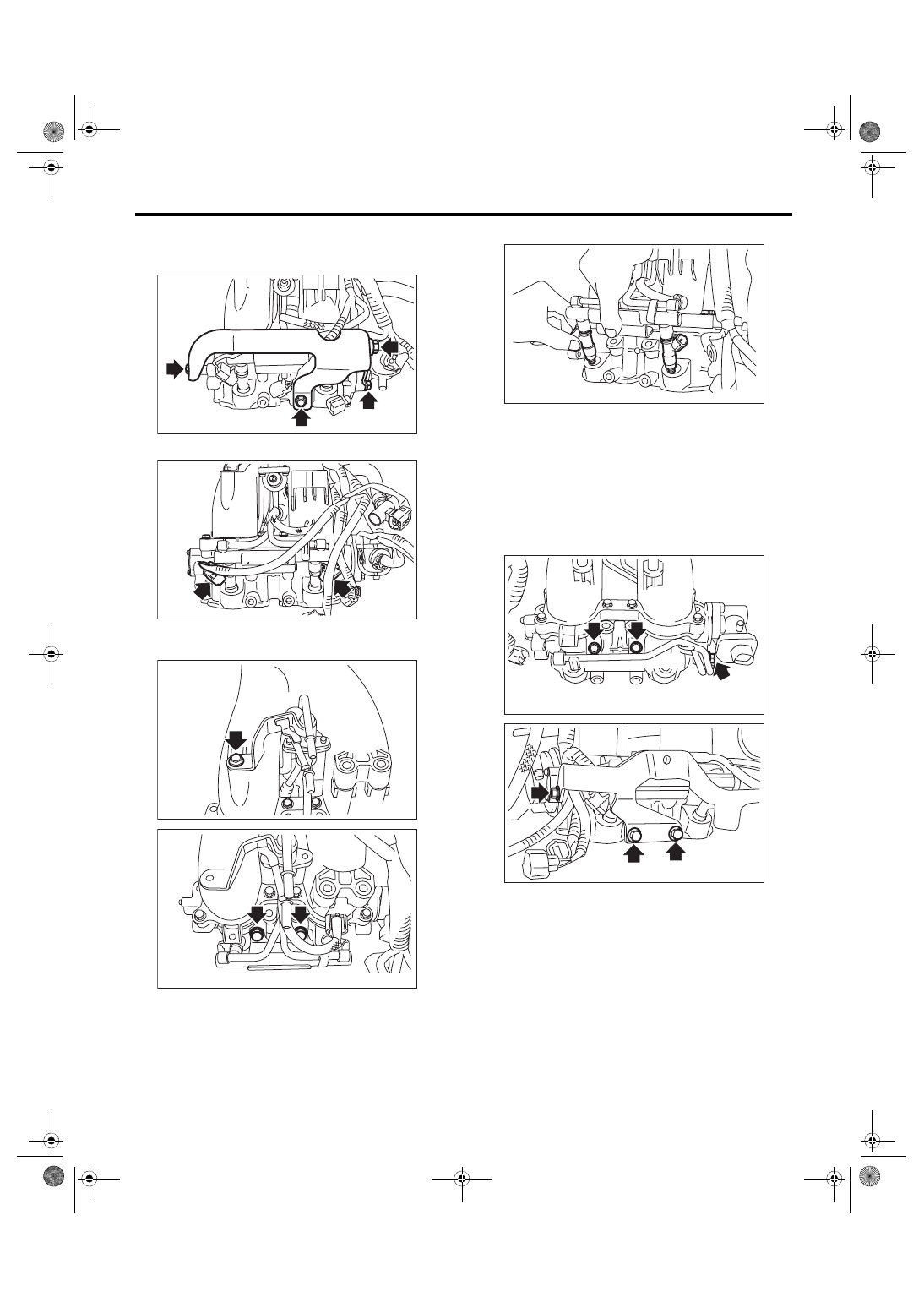
11.Fuel Injector
A: REMOVAL
1. RH SIDE
1) Release the fuel pressure. <Ref. to FU(w/o STI)-
65, RELEASING OF FUEL PRESSURE, PROCE-
2) Disconnect the ground cable from battery.
3) Open the fuel filler lid and remove the fuel filler
cap.
4) Remove the intake manifold. <Ref. to FU(w/o
STI)-18, REMOVAL, Intake Manifold.>
5) Remove the fuel pipe protector RH from the in-
take manifold.
6) Disconnect the connector from fuel injector.
7) Remove the bolt which holds fuel injector pipe
RH onto intake manifold.
8) Remove the fuel injector.
2. LH SIDE
1) Release the fuel pressure. <Ref. to FU(w/o STI)-
65, RELEASING OF FUEL PRESSURE, PROCE-
2) Disconnect the ground cable from battery.
3) Open the fuel filler lid and remove the fuel filler
cap.
4) Remove the intake manifold. <Ref. to FU(w/o
STI)-18, REMOVAL, Intake Manifold.>
IN-00203
FU-06561
FU-06548
FU-03089
FU-03094
IN-00203
FU(w/o STI)-46
Fuel Injector
FUEL INJECTION (FUEL SYSTEMS)
5) Remove the engine ground terminal from the
fuel pipe protector LH and remove the fuel pipe pro-
tector LH from the intake manifold.
6) Disconnect the connector from fuel injector.
7) Remove the bolt which holds fuel injector pipe
LH onto intake manifold.
8) Remove the fuel injector.
B: INSTALLATION
1. RH SIDE
Install in the reverse order of removal.
NOTE:
Use new O-rings, rubbers and seal rings.
Tightening torque:
19 N·m (1.9 kgf-m, 14.0 ft-lb)
FU-06540
FU-06549
FU-05752
FU-04299
FU-03091
FU-03089
FU-06550
Нет комментариевНе стесняйтесь поделиться с нами вашим ценным мнением.
Текст