Subaru Impreza 3 / Impreza WRX / Impreza WRX STI. Service manual — part 127
FU(w/o STI)-35
Crankshaft Position Sensor
FUEL INJECTION (FUEL SYSTEMS)
5. Crankshaft Position Sensor
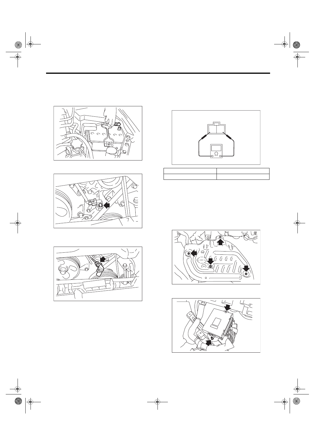
A: REMOVAL
1) Remove the collector cover.
2) Disconnect the ground cable from battery.
3) Remove the bolt which secures crankshaft posi-
tion sensor to oil pump.
4) Remove the crankshaft position sensor, and dis-
connect the connector from the crankshaft position
sensor.
B: INSTALLATION
Install in the reverse order of removal.
Tightening torque:
6.4 N·m (0.7 kgf-m, 4.7 ft-lb)
C: INSPECTION
1. CRANKSHAFT POSITION SENSOR
(METHOD WITH CIRCUIT TESTER)
Measure the resistance between crankshaft posi-
tion sensor terminals.
2. CRANKSHAFT POSITION SENSOR
(METHOD WITH OSCILLOSCOPE)
1) Prepare an oscilloscope.
2) Remove the lower inner trim of passenger’s
side. <Ref. to EI-57, REMOVAL, Lower Inner
3) Turn over the floor mat of passenger’s seat.
4) Remove the protect cover.
5) Remove the nuts and bolts which hold the ECM
to the bracket.
IN-00203
FU-05818
FU-05348
Terminal No.
Standard
1 and 2
2.04±0.204 kΩ
2 1
EC-02428
FU-03416
FU-03417
FU(w/o STI)-36
Crankshaft Position Sensor
FUEL INJECTION (FUEL SYSTEMS)
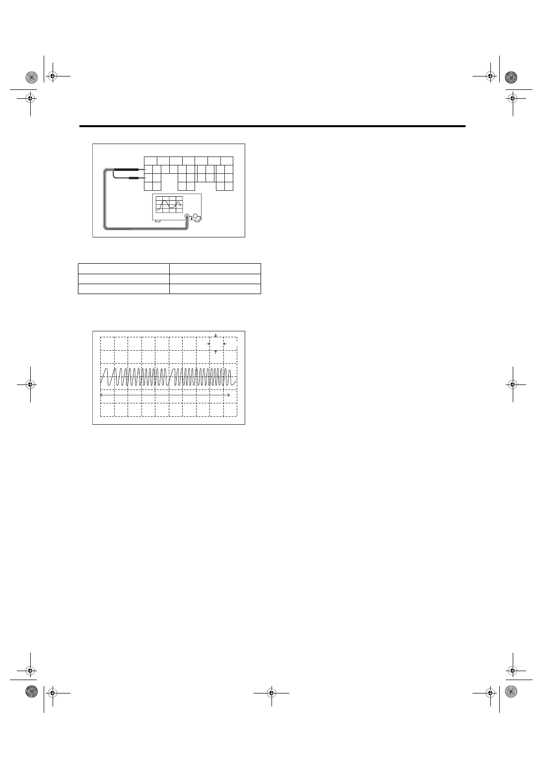
6) Connect the probe to ECM connector.
7) Start the engine and let it idle.
8) Check the pattern is the same as the waveform
and voltage shown below.
9) After inspection, install the related parts in the
reverse order of removal.
Tightening torque:
7.5 N·m (0.8 kgf-m, 5.5 ft-lb)
3. OTHER INSPECTIONS
Check that the crankshaft position sensor has no
deformation, cracks or other damages.
(A) To ECM connector
Terminal No.
Probe
17
+
25
–
(A) One crankshaft rotation
5
6
7
8
2
1
9
4
3
10
22
23
11
12
13
14
15
24
25
26
16
17
18
19
20
21
27
28
29
30
31
FU-04758
(A)
FU-04057
5V
0
10ms
(A)
FU(w/o STI)-37
Camshaft Position Sensor
FUEL INJECTION (FUEL SYSTEMS)
6. Camshaft Position Sensor
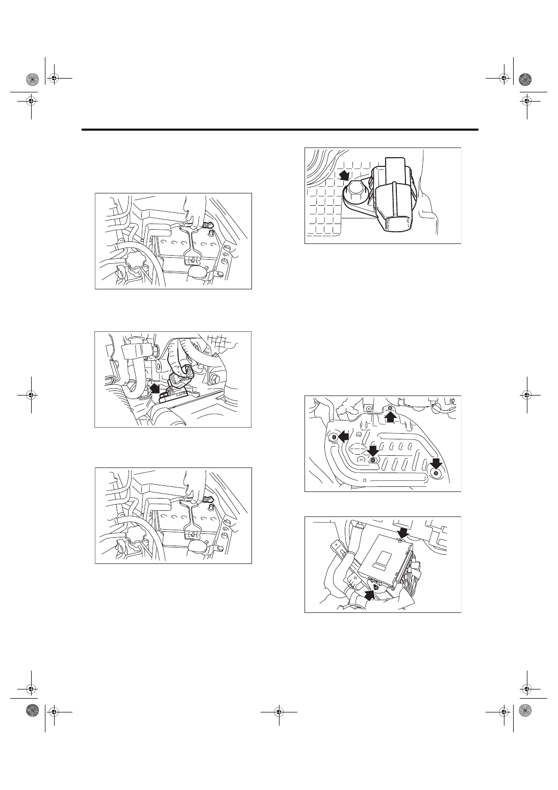
A: REMOVAL
1. CAMSHAFT POSITION SENSOR RH
1) Disconnect the ground cable from battery.
2) Disconnect the connector (A) from the camshaft
position sensor RH, and remove the camshaft po-
sition sensor RH from the rear side of the cylinder
head.
2. CAMSHAFT POSITION SENSOR LH
1) Remove the collector cover.
2) Disconnect the ground cable from battery.
3) Remove the intake manifold. <Ref. to FU(w/o
STI)-18, REMOVAL, Intake Manifold.>
4) Remove the camshaft position sensor LH.
B: INSTALLATION
Install in the reverse order of removal.
Tightening torque:
6.4 N·m (0.7 kgf-m, 4.7 ft-lb)
C: INSPECTION
1. CAMSHAFT POSITION SENSOR (METH-
OD WITH OSCILLOSCOPE)
1) Prepare an oscilloscope.
2) Remove the lower inner trim of passenger’s
side. <Ref. to EI-57, REMOVAL, Lower Inner
3) Turn over the floor mat of passenger’s seat.
4) Remove the protect cover.
5) Remove the nuts and bolts which hold the ECM
to the bracket.
IN-00203
FU-05835
(A)
IN-00203
FU-05841
FU-03416
FU-03417
FU(w/o STI)-38
Camshaft Position Sensor
FUEL INJECTION (FUEL SYSTEMS)
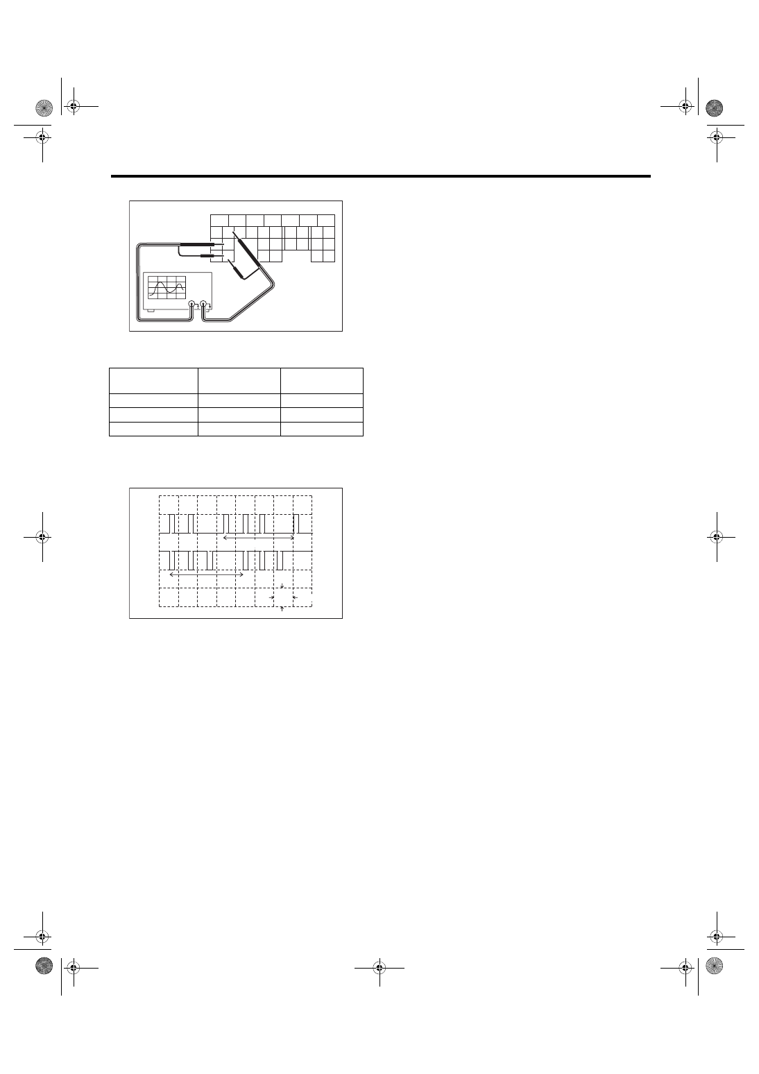
6) Connect the probe to ECM connector.
7) Start the engine and let it idle.
8) Check the pattern is the same as the waveform
and voltage shown below.
9) After inspection, install the related parts in the
reverse order of removal.
Tightening torque:
7.5 N·m (0.8 kgf-m, 5.5 ft-lb)
2. OTHER INSPECTIONS
Check that the camshaft position sensor has no de-
formation, cracks or other damages.
(A) To ECM connector
Camshaft position
sensor
Terminal No.
Probe
RH
24
+
LH
16
+
RH and LH
30
–
(A) One camshaft rotation
5
6
7
8
2
1
9
4
3
10
22
23
11
12
13
14
15
24
25
26
16
17
18
19
20
21
27
28
29
30
31
(A)
FU-04757
FU-04060
LH
5V
50ms
0
RH
0
(A)
(A)
Нет комментариевНе стесняйтесь поделиться с нами вашим ценным мнением.
Текст