Subaru Impreza 3 / Impreza WRX / Impreza WRX STI. Service manual — part 126
FU(w/o STI)-31
Intake Manifold
FUEL INJECTION (FUEL SYSTEMS)
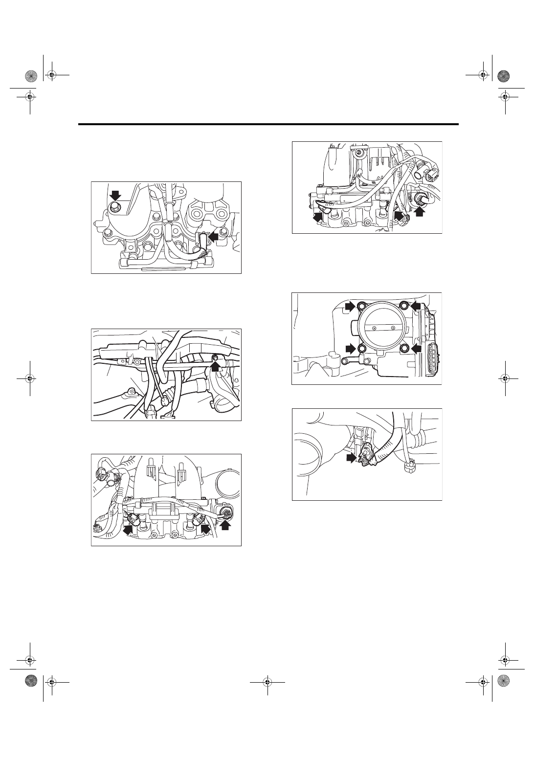
9) Secure the fuel injector pipe LH to intake mani-
fold with bolt, and connect the pressure regulator
vacuum hose to the intake manifold.
Tightening torque:
6.4 N·m (0.7 kgf-m, 4.7 ft-lb)
10) Install the PCV pipe (A), harness assembly (B),
intake duct (C), brake booster vacuum hose (D)
and vacuum hose (E) to the intake manifold.
Tightening torque:
6.4 N·m (0.7 kgf-m, 4.7 ft-lb)
11) Connect the connector to the fuel injector and
the tumble generator valve assembly.
• RH side
• LH side
12) Install the throttle body to the intake manifold.
NOTE:
Use new O-rings.
Tightening torque:
8 N·m (0.8 kgf-m, 5.9 ft-lb)
13) Connect the connector to the throttle position
sensor.
FU-06544
FU-06543
(C)
(A)
(D)
(E)
(B)
FU-06541
FU-06542
FU-05674
FU-05673
FU(w/o STI)-32
Intake Manifold
FUEL INJECTION (FUEL SYSTEMS)
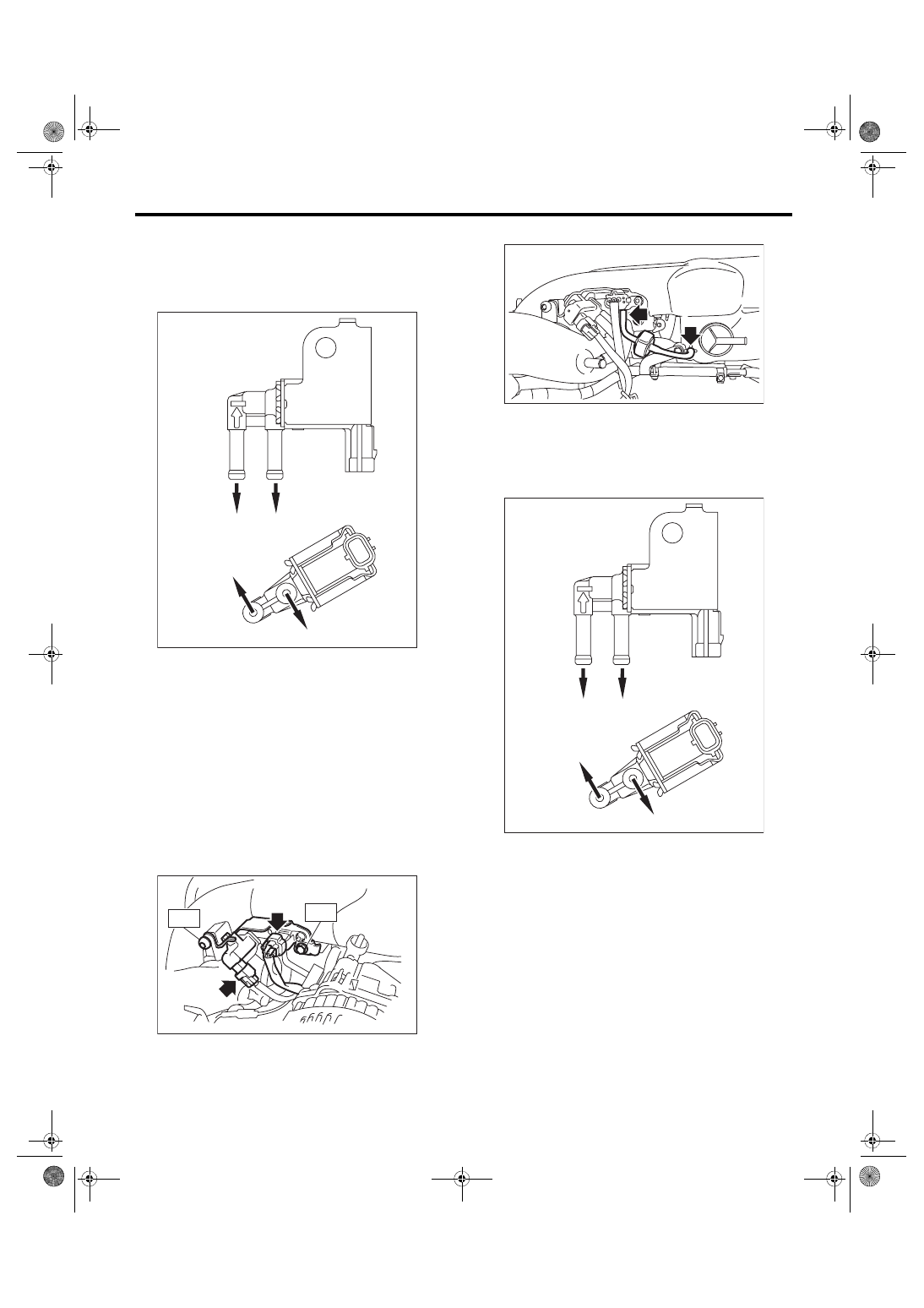
14) Connect the vacuum hose to the intake duct
and the fuel pipe, then connect the connector to the
purge control solenoid valve 2.
NOTE:
Connect the vacuum hose as shown in the figure.
15) Install the solenoid valve bracket assembly to
the intake manifold, and connect the connector to
the wastegate control solenoid valve and the man-
ifold absolute pressure sensor.
Tightening torque:
T1: 17 N·m (1.7 kgf-m, 12.5 ft-lb)
T2: 19 N·m (1.9 kgf-m, 14.0 ft-lb)
16) Connect the filter assembly.
17) Connect the vacuum hose and the connector
the fuel pipe, and install the purge control solenoid
valve 1 to the intake manifold.
NOTE:
Connect the vacuum hose as shown in the figure.
(A) Purge control solenoid valve 1
(B) Purge control solenoid valve 2
(a) To intake manifold
(b) To intake duct
(c) To fuel pipe
(A)
(B)
(b)
(c)
(c)
(a)
EC-02517
FU-05439
T1
T2
(A) Purge control solenoid valve 1
(B) Purge control solenoid valve 2
(a) To intake manifold
(b) To intake duct
(c) To fuel pipe
FU-05342
(A)
(B)
(b)
(c)
(c)
(a)
EC-02517
FU(w/o STI)-33
Intake Manifold
FUEL INJECTION (FUEL SYSTEMS)
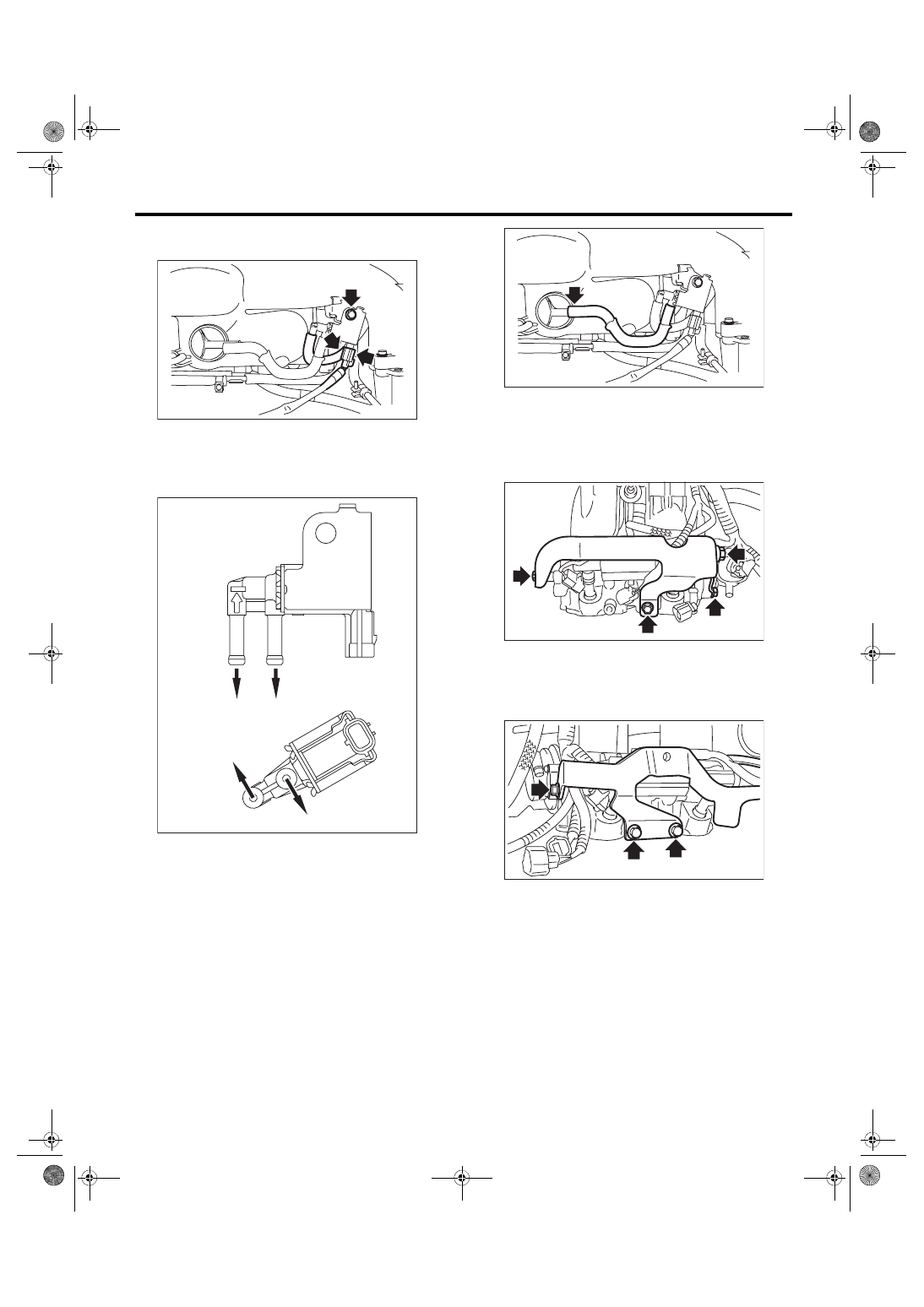
Tightening torque:
6.4 N·m (0.7 kgf-m, 4.7 ft-lb)
18) Connect the vacuum hose to the intake mani-
fold.
NOTE:
Connect the vacuum hose as shown in the figure.
19) Install the fuel pipe protector LH to the intake
manifold, and install the engine ground terminal to
the fuel pipe protector LH.
Tightening torque:
19 N·m (1.9 kgf-m, 14.0 ft-lb)
20) Install the fuel pipe protector RH to the intake
manifold.
Tightening torque:
19 N·m (1.9 kgf-m, 14.0 ft-lb)
E: INSPECTION
1) Check that the intake manifold and fuel pipe
have no deformation, cracks and other damages.
2) Check that the hose has no cracks, damage or
loose part.
(A) Purge control solenoid valve 1
(B) Purge control solenoid valve 2
(a) To intake manifold
(b) To intake duct
(c) To fuel pipe
FU-05441
(A)
(B)
(b)
(c)
(c)
(a)
EC-02517
FU-05367
FU-06540
FU-06561
FU(w/o STI)-34
Engine Coolant Temperature Sensor
FUEL INJECTION (FUEL SYSTEMS)
4. Engine Coolant Temperature
Sensor
A: REMOVAL
1) Disconnect the ground cable from battery.
2) Remove the generator. <Ref. to SC(STI)-21,
3) Drain engine coolant. <Ref. to CO(w/o STI)-13,
DRAINING OF ENGINE COOLANT, REPLACE-
4) Disconnect the connector (A) from the engine
coolant temperature sensor, and remove the en-
gine coolant temperature sensor.
B: INSTALLATION
Install in the reverse order of removal.
NOTE:
Use a new gasket.
Tightening torque:
18 N·m (1.8 kgf-m, 13.3 ft-lb)
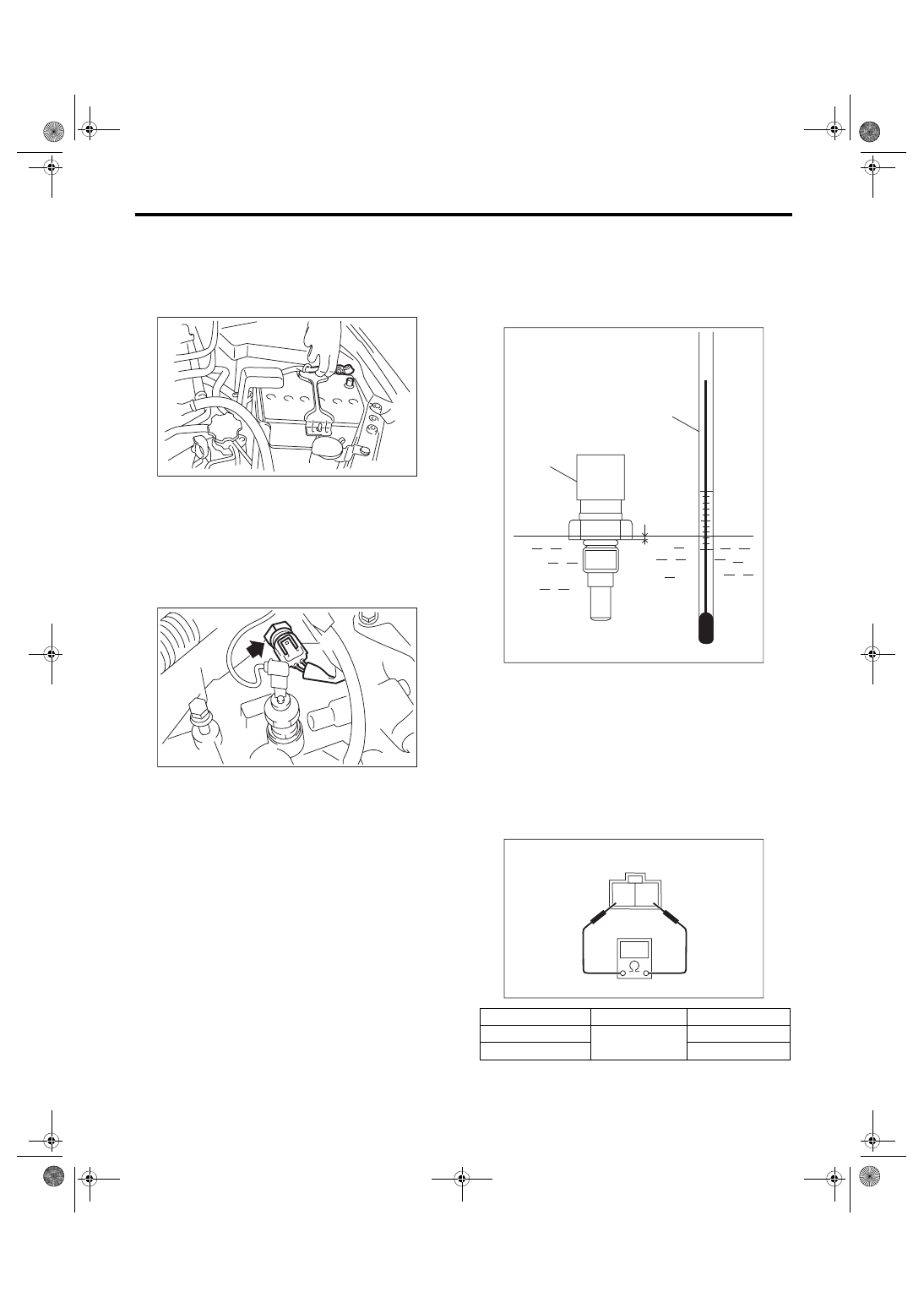
C: INSPECTION
1) Check that the engine coolant temperature sen-
sor has no deformation, cracks or other damages.
2) Immerse the engine coolant temperature sensor
and a thermometer in water.
CAUTION:
Take care not to allow water to get into the en-
gine coolant temperature sensor connector.
Completely remove any water inside.
3) Raise water temperature gradually, measure the
resistance between the engine coolant tempera-
ture sensor terminals when the temperature is
20°C (68°F) and 80°C (176°F).
NOTE:
Agitate the water for even temperature distribution.
IN-00203
FU-05830
(A)
(A) Thermometer
(B) Engine coolant temperature sensor
(C) Hexagonal part height: to approx.
1
/
3
Water temperature
Terminal No.
Standard
20°C (68°F)
1 and 2
2.45±0.2 kΩ
80°C (176°F)
0.318±0.013 kΩ
FU-04053
(A)
(B)
(C)
2 1
EC-02428
Нет комментариевНе стесняйтесь поделиться с нами вашим ценным мнением.
Текст