Subaru Impreza 3 / Impreza WRX / Impreza WRX STI. Service manual — part 30
FU(STI)-32
Intake Manifold
FUEL INJECTION (FUEL SYSTEMS)
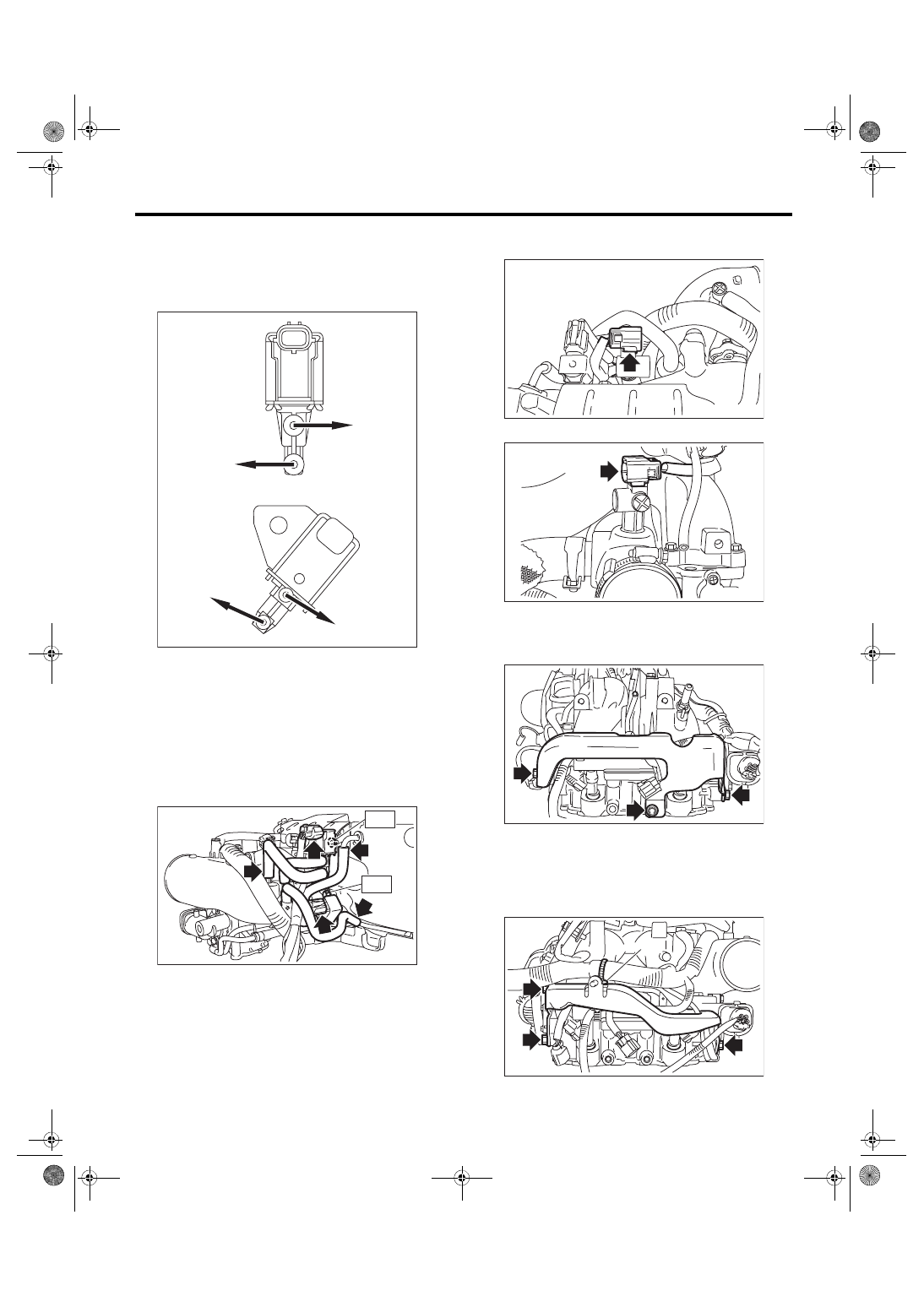
19) Install purge control solenoid valve 1 and purge
control solenoid valve 2.
NOTE:
Connect the vacuum hose and vacuum control
hose as shown in the figure.
Tightening torque:
T1: 6.4 N·m (0.7 kgf-m, 4.7 ft-lb)
T2: 16 N·m (1.6 kgf-m, 11.8 ft-lb)
20) Attach the connector to the PCV hose assem-
bly.
21) Install the connector to the intake duct.
22) Install the fuel pipe protector LH.
Tightening torque:
19 N·m (1.9 kgf-m, 14.0 ft-lb)
23) Install the fuel pipe protector RH, and secure
the engine harness to the fuel pipe protector RH
using the clip (A).
Tightening torque:
19 N·m (1.9 kgf-m, 14.0 ft-lb)
(A) Purge control solenoid valve 1
(B) Purge control solenoid valve 2
(a) To intake duct
(b) To intake manifold
(c) To branching pipe → fuel pipe
(c)
(b)
(a)
(B)
(A)
(c)
FU-04417
FU-06582
T2
T1
FU-06576
FU-05921
FU-06591
FU-06575
(A)
FU(STI)-33
Intake Manifold
FUEL INJECTION (FUEL SYSTEMS)
E: INSPECTION
1) Check that the intake manifold and fuel pipe
have no deformation, cracks and other damages.
2) Check that the hose has no cracks, damage or
loose part.
FU(STI)-34
Engine Coolant Temperature Sensor
FUEL INJECTION (FUEL SYSTEMS)
4. Engine Coolant Temperature
Sensor
A: REMOVAL
1) Disconnect the ground cable from battery.
2) Remove the generator. <Ref. to SC(STI)-21,
3) Drain engine coolant. <Ref. to CO(STI)-13,
DRAINING OF ENGINE COOLANT, REPLACE-
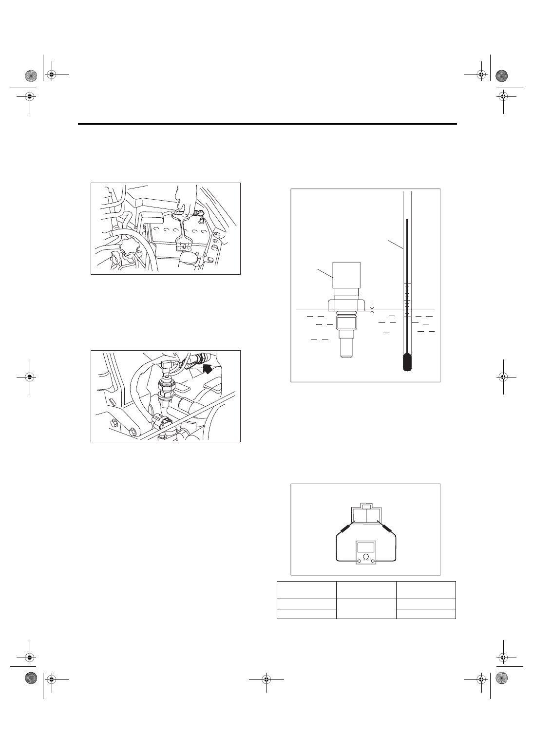
4) Disconnect the connector (A) from the engine
coolant temperature sensor, and remove the en-
gine coolant temperature sensor.
B: INSTALLATION
Install in the reverse order of removal.
NOTE:
Use a new gasket.
Tightening torque:
18 N·m (1.8 kgf-m, 13.3 ft-lb)
C: INSPECTION
1) Check that the engine coolant temperature sen-
sor has no deformation, cracks or other damages.
2) Immerse the engine coolant temperature sensor
and a thermometer in water.
CAUTION:
Take care not to allow water to get into the en-
gine coolant temperature sensor connector.
Completely remove any water inside.
3) Raise water temperature gradually, measure the
resistance between the engine coolant tempera-
ture sensor terminals when the temperature is
20°C (68°F) and 80°C (176°F).
NOTE:
Agitate the water for even temperature distribution.
IN-00203
(A)
FU-05796
(A) Thermometer
(B) Engine coolant temperature sensor
(C) Hexagonal part height: To approx.
1
/
3
Water tempera-
ture
Terminal No.
Standard
20°C (68°F)
1 and 2
2.45±0.2 kΩ
80°C (176°F)
0.318±0.013 kΩ
FU-04053
(A)
(B)
(C)
2 1
EC-02428
FU(STI)-35
Crankshaft Position Sensor
FUEL INJECTION (FUEL SYSTEMS)
5. Crankshaft Position Sensor
A: REMOVAL
1) Disconnect the ground cable from battery.
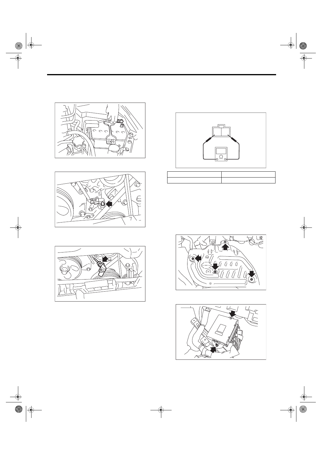
2) Remove the bolt which secures crankshaft posi-
tion sensor to oil pump.
3) Remove the crankshaft position sensor, and dis-
connect the connector from the crankshaft position
sensor.
B: INSTALLATION
Install in the reverse order of removal.
Tightening torque:
6.4 N·m (0.7 kgf-m, 4.7 ft-lb)
C: INSPECTION
1. CRANKSHAFT POSITION SENSOR
(METHOD WITH CIRCUIT TESTER)
Measure the resistance between crankshaft posi-
tion sensor terminals.
2. CRANKSHAFT POSITION SENSOR
(METHOD WITH OSCILLOSCOPE)
1) Prepare an oscilloscope.
2) Remove the lower inner trim of passenger’s
side. <Ref. to EI-57, REMOVAL, Lower Inner
3) Turn over the floor mat of passenger’s seat.
4) Remove the protect cover.
5) Remove the nuts and bolts which hold the ECM
to the bracket.
IN-00203
FU-05818
FU-05348
Terminal No.
Standard
1 and 2
2.04±0.204 kΩ
2 1
EC-02428
FU-03416
FU-03417
Нет комментариевНе стесняйтесь поделиться с нами вашим ценным мнением.
Текст