Subaru Impreza 3 / Impreza WRX / Impreza WRX STI. Service manual — part 31
FU(STI)-36
Crankshaft Position Sensor
FUEL INJECTION (FUEL SYSTEMS)
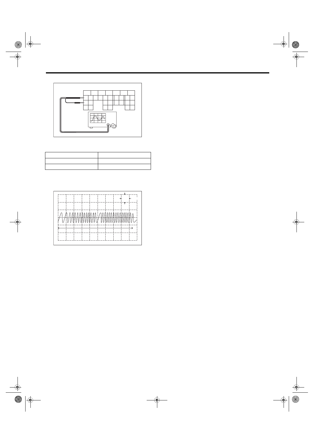
6) Connect the probe to ECM connector.
7) Start the engine and let it idle.
8) Check the pattern is the same as the waveform
and voltage shown below.
9) After inspection, install the related parts in the
reverse order of removal.
Tightening torque:
7.5 N·m (0.8 kgf-m, 5.5 ft-lb)
3. OTHER INSPECTIONS
Check that the crankshaft position sensor has no
deformation, cracks or other damages.
(A) To ECM connector
Terminal No.
Probe
17
+
25
–
(A) One crankshaft rotation
5
6
7
8
2
1
9
4
3
10
22
23
11
12
13
14
15
24
25
26
16
17
18
19
20
21
27
28
29
30
31
FU-04758
(A)
FU-04057
5V
0
10ms
(A)
FU(STI)-37
Camshaft Position Sensor
FUEL INJECTION (FUEL SYSTEMS)
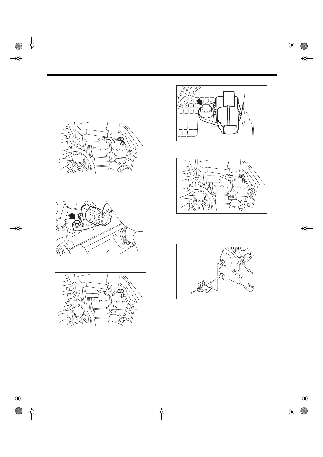
6. Camshaft Position Sensor
A: REMOVAL
1. INTAKE SIDE
• Camshaft position sensor RH
1) Disconnect the ground cable from battery.
2) Disconnect the connector (A) from the camshaft
position sensor RH, and remove the camshaft po-
sition sensor RH from the rear side of the cylinder
head.
• Camshaft position sensor LH
1) Disconnect the ground cable from battery.
2) Remove the intake manifold. <Ref. to FU(STI)-
17, REMOVAL, Intake Manifold.>
3) Remove the camshaft position sensor LH.
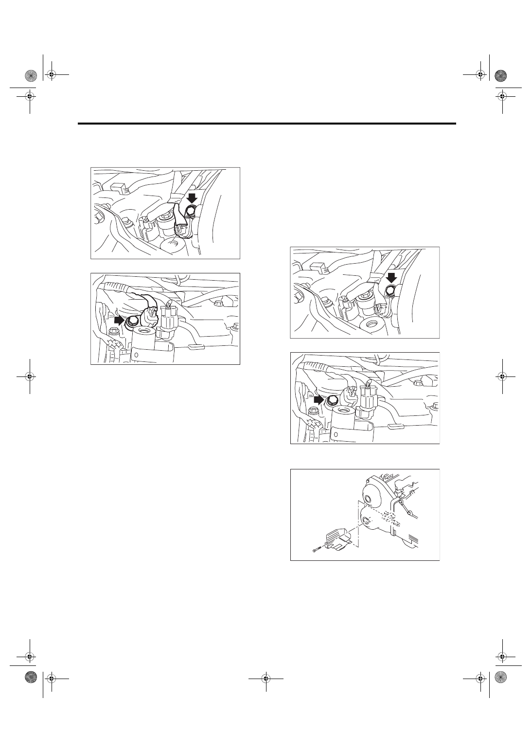
2. EXHAUST SIDE
1) Disconnect the ground cable from battery.
2) Lift up the vehicle.
3) Remove the under cover. <Ref. to EI-28, RE-
4) Remove the engine harness cover. (right side
only.)
IN-00203
FU-05840
(A)
IN-00203
FU-05841
IN-00203
FU-03616
FU(STI)-38
Camshaft Position Sensor
FUEL INJECTION (FUEL SYSTEMS)
5) Disconnect connector (A) from the camshaft po-
sition sensor, and remove the camshaft position
sensor from under the cylinder head.
• RH side
• LH side
B: INSTALLATION
1. INTAKE SIDE
Install in the reverse order of removal.
Tightening torque:
6.4 N·m (0.7 kgf-m, 4.7 ft-lb)
2. EXHAUST SIDE
Install in the reverse order of removal.
Tightening torque:
6.4 N·m (0.7 kgf-m, 4.7 ft-lb)
• RH side
• LH side
Tightening torque:
5 N·m (0.5 kgf-m, 3.7 ft-lb)
FU-05801
(A)
FU-05826
(A)
FU-05793
FU-05827
FU-03616

FU(STI)-39
Camshaft Position Sensor
FUEL INJECTION (FUEL SYSTEMS)
C: INSPECTION
1. CAMSHAFT POSITION SENSOR (METH-
OD WITH OSCILLOSCOPE)
1) Prepare an oscilloscope.
2) Remove the lower inner trim of passenger’s
side. <Ref. to EI-57, REMOVAL, Lower Inner
3) Turn over the floor mat of passenger’s seat.
4) Remove the protect cover.
5) Remove the nuts and bolts which hold the ECM
to the bracket.
6) Connect the probe to ECM connector.
• Intake camshaft position sensor
• Exhaust camshaft position sensor
7) Start the engine and let it idle.
8) Check the pattern is the same as the waveform
and voltage shown below.
9) After inspection, install the related parts in the
reverse order of removal.
Tightening torque:
7.5 N·m (0.8 kgf-m, 5.5 ft-lb)
2. OTHER INSPECTIONS
Check that the camshaft position sensor has no de-
formation, cracks or other damages.
(A) To ECM connector
FU-03416
FU-03417
5
6
7
8
2
1
9
4
3
10
22
23
11
12
13
14
15
24
25
26
16
17
18
19
20
21
27
28
29
30
31
(A)
FU-04757
(A) To ECM connector
Camshaft position
sensor
Terminal No.
Probe
Intake
RH
24
+
LH
16
+
Exhaust
RH
23
+
LH
29
+
RH and LH
30
–
(A) One camshaft rotation
(B) Intake camshaft position sensor RH
(C) Intake camshaft position sensor LH
(D) Exhaust camshaft position sensor RH
(E) Exhaust camshaft position sensor LH
5
6
7
8
2
1
9
4
3
10
22
23
11
12
13
14
15
24
25
26
16
17
18
19
20
21
27
28
29
30
31
(A)
FU-04762
FU-04763
0
0
0
0
(A)
10ms
5V
(B)
(C)
(D)
(E)
Нет комментариевНе стесняйтесь поделиться с нами вашим ценным мнением.
Текст