Subaru Impreza 3 / Impreza WRX / Impreza WRX STI. Service manual — part 28
FU(STI)-24
Intake Manifold
FUEL INJECTION (FUEL SYSTEMS)
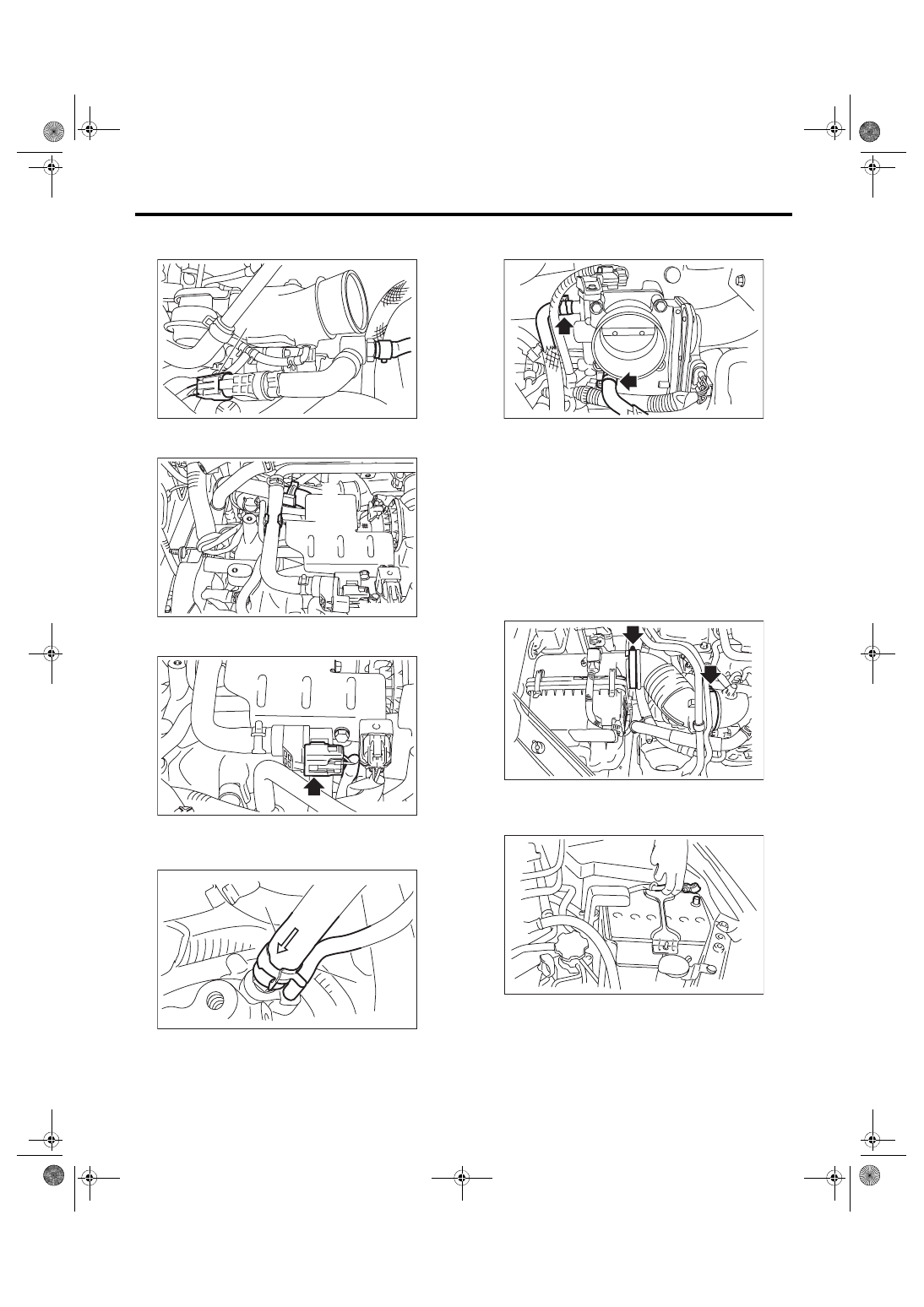
19) Connect the vacuum hose (A) and connector
(B) to the PCV hose assembly B.
20) Install the vacuum hose to clip (B), and install
the PCV hose assembly A to clip (A).
21) Connect the connector to the PCV hose as-
sembly A.
22) Connect the brake booster vacuum hose (A)
and pressure regulator vacuum hose (B) to the in-
take manifold.
23) Connect the engine coolant hoses to throttle
body.
24) Install the A/C pressure hoses to A/C compres-
sor. <Ref. to AC-41, INSTALLATION, Hose and
25) Install the coolant filler tank. <Ref. to CO(STI)-
28, INSTALLATION, Coolant Filler Tank.>
26) Install the generator. <Ref. to SC(STI)-21, IN-
27) Install the intercooler. <Ref. to IN(STI)-13, IN-
28) Install the air intake boot.
Tightening torque:
2.5 N·m (0.3 kgf-m, 1.8 ft-lb)
29) Install the air intake duct. <Ref. to IN(STI)-10,
INSTALLATION, Air Intake Duct.>
30) Connect the battery ground terminal.
31) Lift up the vehicle.
32) Install the under cover. <Ref. to EI-28, INSTAL-
33) Lower the vehicle.
(A)
(B)
FU-06566
FU-06568
(A)
(B)
FU-06567
ME-05007
E N G
(A)
(B)
FU-05761
LU-02413
IN-00203
FU(STI)-25
Intake Manifold
FUEL INJECTION (FUEL SYSTEMS)
34) Install the V-belt cover.
Tightening torque:
13 N·m (1.3 kgf-m, 9.6 ft-lb)
35) Fill engine coolant. <Ref. to CO(STI)-13, FILL-
ING OF ENGINE COOLANT, REPLACEMENT,
36) Charge the A/C system with refrigerant. <Ref.
to AC-20, PROCEDURE, Refrigerant Charging
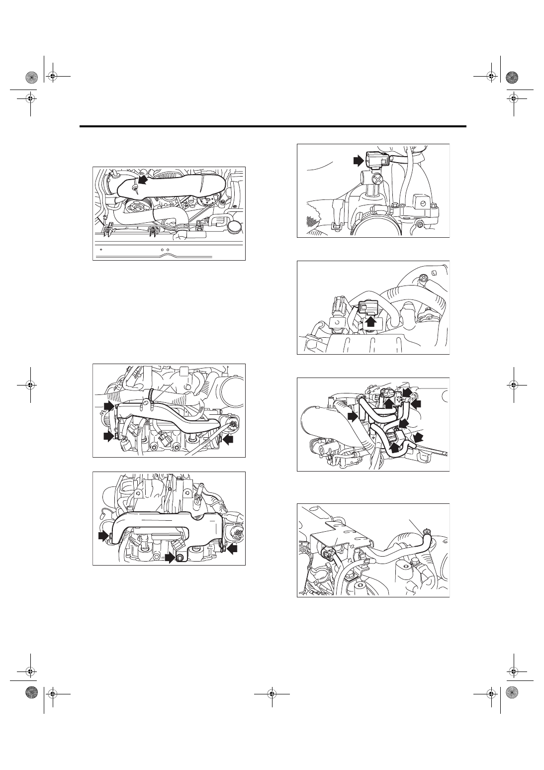
C: DISASSEMBLY
1) Remove clamp (A) holding the fuel pipe protec-
tor RH to the engine harness, and remove the fuel
pipe protector RH.
2) Remove the fuel pipe protector LH.
3) Remove the connector from the intake duct.
4) Remove the connector from the PCV hose as-
sembly.
5) Remove purge control solenoid valve 1 (A) and
purge control solenoid valve 2 (B).
6) Disconnect the connector (A) from the waste-
gate control solenoid valve, and disconnect the
vacuum hose (B) from the intake duct.
FU-03487
FU-06575
(A)
FU-06591
FU-05921
FU-06576
FU-06577
(A)
(B)
FU-06578
(A)
(B)
FU(STI)-26
Intake Manifold
FUEL INJECTION (FUEL SYSTEMS)
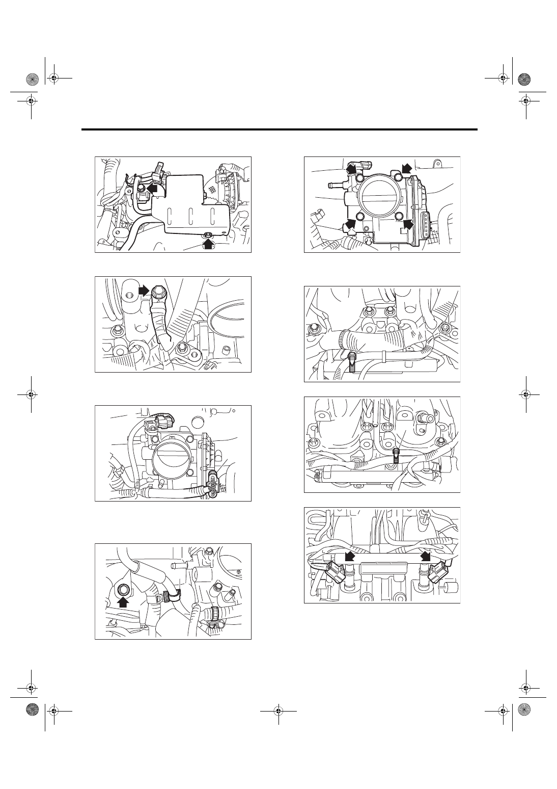
7) Remove the solenoid valve bracket together with
the wastegate control solenoid valve.
8) Remove the engine ground terminals from the
intake manifold.
9) Disconnect the connector (A) from the throttle
position sensor, and the connector (B) from the
manifold pressure sensor.
10) Remove clip (A) holding the engine harness
and vacuum hose, clip (B) holding the engine har-
ness to the engine harness stay, and the bolt hold-
ing the engine harness to the intake manifold.
11) Remove the throttle body from the intake man-
ifold.
12) Remove the harness band (A) which holds the
engine harness to the fuel injector pipe.
• RH side
• LH side
13) Disconnect the connector from fuel injector.
FU-06579
FU-03588
FU-05918
(B)
(A)
FU-03565
(A)
(B)
FU-05692
FU-05919
(A)
FU-05920
(A)
FU-03508
FU(STI)-27
Intake Manifold
FUEL INJECTION (FUEL SYSTEMS)
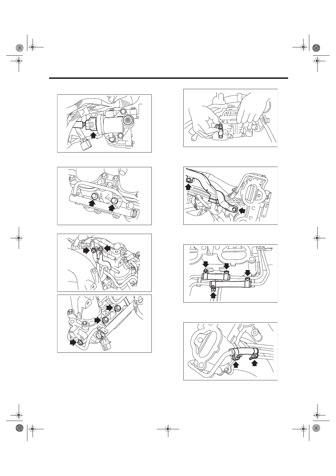
14) Disconnect the connector from the tumble gen-
erator valve assembly.
15) Remove the bolts which hold fuel injector pipe.
• RH side
• LH side
16) Remove the fuel injector.
17) Remove the harness brackets holding the en-
gine harness to the intake manifold, and remove
the engine harness.
18) Loosen the clamp holding the RH side fuel
hose to the fuel injector pipe RH, and remove the
fuel injector pipe RH.
19) Loosen the clamp holding the LH side fuel hose
to the fuel injector pipe LH, and remove the fuel in-
jector pipe LH.
FU-04604
FU-03512
FU-03594
FU-03595
FU-03513
FU-03567
FU-04605
FU-04606
Нет комментариевНе стесняйтесь поделиться с нами вашим ценным мнением.
Текст