Subaru Impreza 3 / Impreza WRX / Impreza WRX STI. Service manual — part 29
FU(STI)-28
Intake Manifold
FUEL INJECTION (FUEL SYSTEMS)
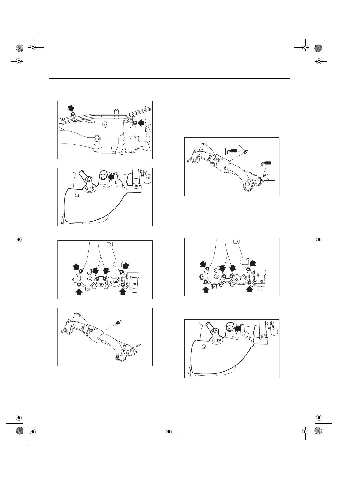
20) Remove the bolts holding the fuel pipe assem-
bly to the intake manifold, and remove the fuel pipe
assembly.
21) Remove the intake duct from intake manifold.
22) Remove the tumble generator valve assembly
from the intake manifold.
23) Remove the nipple from the intake manifold.
D: ASSEMBLY
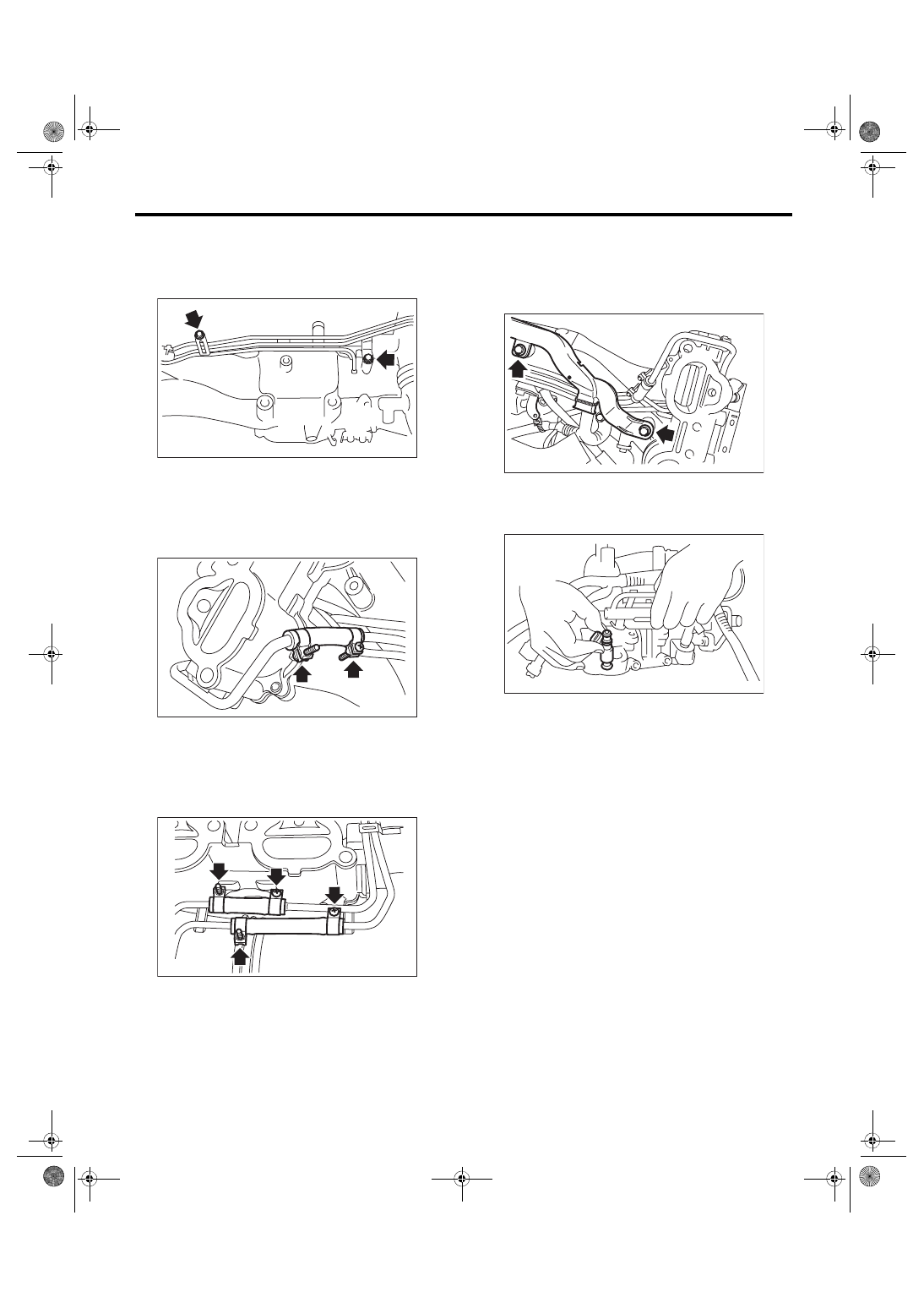
1) Apply liquid gasket to the nipple threads, and in-
stall the nipple to the intake manifold.
Liquid gasket:
THREE BOND 1105 (Part No. 004403010)
Tightening torque:
T1: 17 N·m (1.7 kgf-m, 12.5 ft-lb)
T2: 25 N·m (2.5 kgf-m, 18.4 ft-lb)
2) Install the tumble generator valve assembly onto
intake manifold.
NOTE:
Use a new gasket.
Tightening torque:
8.3 N·m (0.8 kgf-m, 6.1 ft-lb)
3) Install the air intake duct to the intake manifold.
Tightening torque:
17 N·m (1.7 kgf-m, 12.5 ft-lb)
FU-00051
FU-06580
FU-03603
FU-05787
FU-05788
T1
T2
FU-03603
FU-06580
FU(STI)-29
Intake Manifold
FUEL INJECTION (FUEL SYSTEMS)
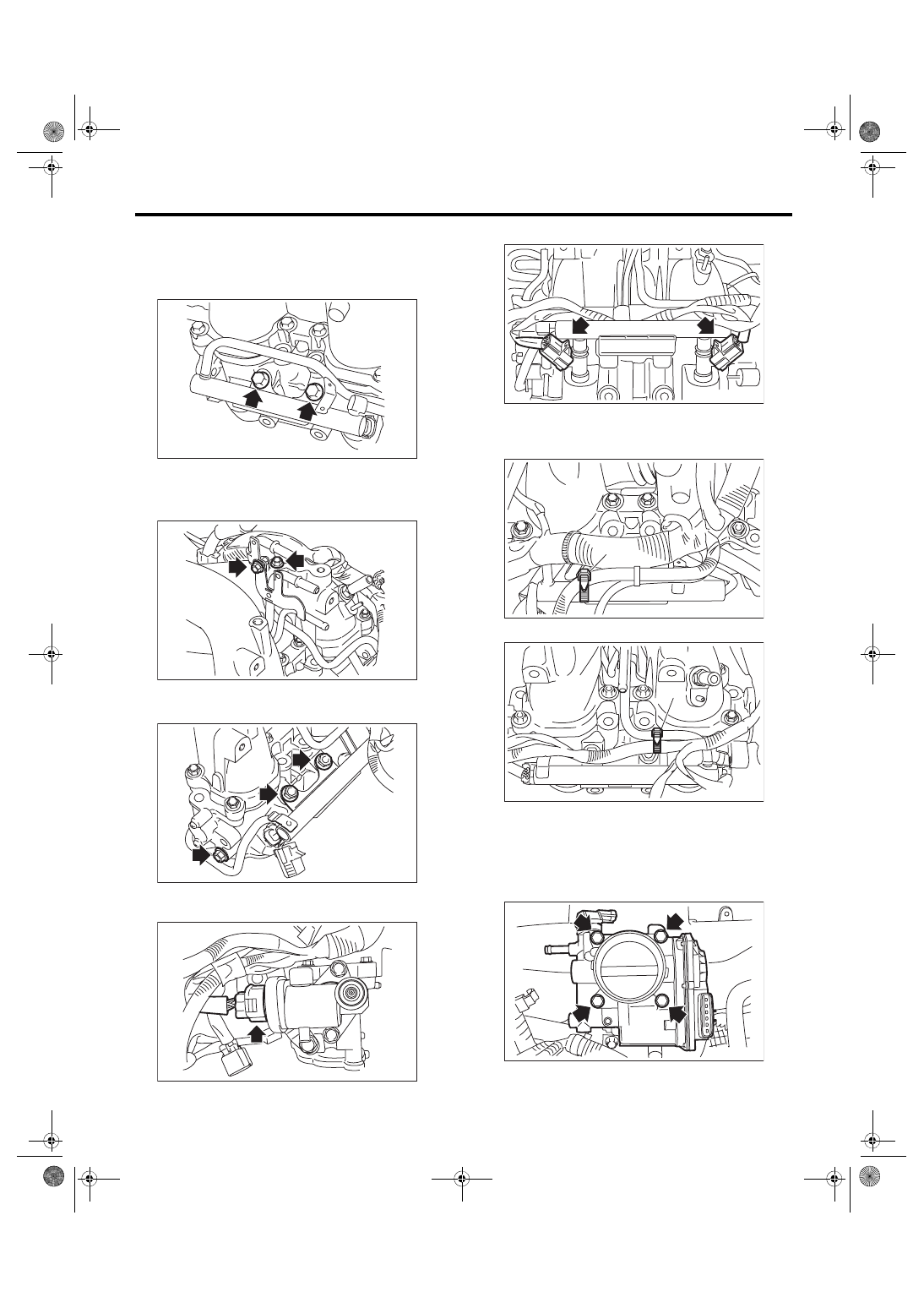
4) Install the fuel pipe assembly to the intake man-
ifold.
Tightening torque:
6.4 N·m (0.7 kgf-m, 4.7 ft-lb)
5) Install the fuel injector pipe LH and connect the
LH side fuel hose to the fuel injector pipe LH. <Ref.
to FU(STI)-97, CONNECTING FUEL DELIVERY
HOSE, FUEL RETURN HOSE AND FUEL HOSE,
INSTALLATION, Fuel Delivery, Return and Evapo-
6) Install the fuel injector pipe RH and connect the
RH side fuel hose to the fuel injector pipe RH. <Ref.
to FU(STI)-97, CONNECTING FUEL DELIVERY
HOSE, FUEL RETURN HOSE AND FUEL HOSE,
INSTALLATION, Fuel Delivery, Return and Evapo-
7) Install the engine harness to the intake manifold
and attach the harness brackets holding the engine
harness.
Tightening torque:
19 N·m (1.9 kgf-m, 14.0 ft-lb)
8) Install the fuel injector.
NOTE:
Use new O-rings.
FU-00051
FU-04606
FU-04605
FU-03567
FU-03513
FU(STI)-30
Intake Manifold
FUEL INJECTION (FUEL SYSTEMS)
9) Install the bolts which hold fuel injector pipe.
• RH side
Tightening torque:
19 N·m (1.9 kgf-m, 14.0 ft-lb)
• LH side
Tightening torque:
6.4 N·m (0.7 kgf-m, 4.7 ft-lb)
Tightening torque:
19 N·m (1.9 kgf-m, 14.0 ft-lb)
10) Connect the connector to the tumble generator
valve assembly.
11) Connect the connectors to the fuel injector.
12) Secure the engine harness to the fuel injector
pipe with the harness band (A).
• RH side
• LH side
13) Install the throttle body to the intake manifold.
NOTE:
Use a new gasket.
Tightening torque:
8 N·m (0.8 kgf-m, 5.9 ft-lb)
FU-03512
FU-03594
FU-03595
FU-04604
FU-03508
FU-05919
(A)
FU-05920
(A)
FU-05692
FU(STI)-31
Intake Manifold
FUEL INJECTION (FUEL SYSTEMS)
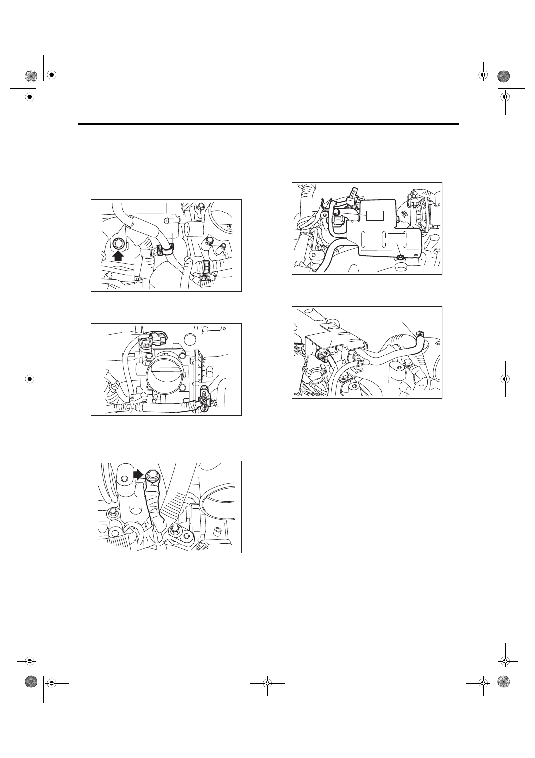
14) Secure the engine harness and vacuum hose
using the clip (A), and secure the engine harness to
the engine harness stay using the clip (B), and in-
stall the bolt which holds the engine harness to the
intake manifold.
Tightening torque:
19 N·m (1.9 kgf-m,14.0 ft-lb)
15) Connect connector (A) to the throttle position
sensor and connector (B) to the manifold pressure
sensor.
16) Install the engine ground terminal to intake
manifold.
Tightening torque:
19 N·m (1.9 kgf-m, 14.0 ft-lb)
17) Install the solenoid valve bracket together with
the wastegate control solenoid valve.
Tightening torque:
T1: 6.4 N·m (0.7 kgf-m, 4.7 ft-lb)
T2: 19 N·m (1.9 kgf-m, 14.0 ft-lb)
18) Connect the vacuum hose (B) to the intake
duct, then connect the connector (A) to the waste-
gate control solenoid valve.
FU-03565
(A)
(B)
FU-05918
(B)
(A)
FU-03588
FU-06581
T1
T2
FU-06578
(A)
(B)
Нет комментариевНе стесняйтесь поделиться с нами вашим ценным мнением.
Текст