Subaru Impreza 3 / Impreza WRX / Impreza WRX STI. Service manual — part 520
VDC-9
VDC Control Module and Hydraulic Control Unit (VDCCM&H/U)
VEHICLE DYNAMICS CONTROL (VDC)
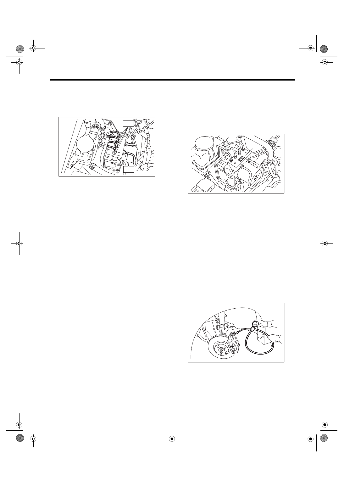
3) Connect the brake pipes to their correct VDC-
CM&H/U positions.
Tightening torque:
T1: 15 N·m (1.53 kgf-m, 11.1 ft-lb)
T2: 19 N·m (1.94 kgf-m, 14 ft-lb)
4) Connect the VDCCM&H/U connector.
NOTE:
• Be sure to remove all foreign matter from inside
the connector before connecting.
• Make sure the VDCCM&H/U connector is se-
curely locked.
5) Bleed air from the brake system. <Ref. to BR-41,
6) Check the parameter to confirm that the applied
models and grades of the relevant vehicle are in-
cluded. <Ref. to VDC(diag)-21, PARAMETER
CHECK, OPERATION, Subaru Select Monitor.>
7) If the applied model and grade of the target ve-
hicle are not included on the {Confirm on parame-
ter} display screen, perform parameter selection
and registration. <Ref. to VDC(diag)-21, PARAME-
TER SELECTION, OPERATION, Subaru Select
Monitor.>
NOTE:
• When the VDCCM&H/U is replaced with a new
part, be sure to perform the selection · registration
operation.
• For the selection and registration of parameter,
the Subaru Select Monitor is required.
• When the registration has not been performed,
the DTC code “Parameter selection error” is detect-
ed together with the ABS/EBD/VDC warning light il-
lumination.
C: INSPECTION
1) Check the condition of connection and settle-
ment of connector.
2) Check the mark used for VDCCM&H/U identifi-
cation.
Refer to “SPECIFICATION” for identification mark.
<Ref. to VDC-2, SPECIFICATION, General De-
1. CHECKING THE HYDRAULIC UNIT ABS
OPERATION BY PRESSURE GAUGE
1) Lift up the vehicle, and then remove the wheel.
2) Remove the air bleeder screws from FL and FR
caliper bodies.
3) Connect two pressure gauges to FL and FR cal-
iper bodies.
CAUTION:
• Use a pressure gauge used exclusively for
brake fluid measurement.
• Do not use the pressure gauge used for the
measurement of transmission oil. Doing so will
cause the piston seal to expand and deform.
NOTE:
Wrap sealing tape around the pressure gauge.
VDC00451
T1
T2
(1) Identification mark
VDC00452
(1)
ABS00134
VDC-10
VDC Control Module and Hydraulic Control Unit (VDCCM&H/U)
VEHICLE DYNAMICS CONTROL (VDC)
4) Bleed air from the pressure gauges and the FL
and FR caliper bodies.
5) Perform ABS sequence control. <Ref. to VDC-
6) When the hydraulic unit begins to work, first the
FL side performs decompression, hold and com-
pression, and then the FR side performs decom-
pression, hold and compression.
7) Read values indicated on the pressure gauge
and check if the fluctuation of the values between
decompression and compression meets the stan-
dard values. Depress the brake pedal and check
that the kick-back is normal, and tightness is nor-
mal.
8) Disconnect the pressure gauges from FL and FR
caliper bodies.
9) Install the air bleeder screws of FL and FR cali-
per bodies.
10) Remove the air bleeder screws from RL and
RR caliper bodies.
11) Connect two pressure gauges to RL and RR
caliper bodies.
12) Bleed air from the brake system. <Ref. to BR-
13) Bleed air from RL and RR caliper bodies, and
pressure gauge.
14) Perform ABS sequence control. <Ref. to VDC-
15) When the hydraulic unit begins to work, first the
RR side performs decompression, hold and com-
pression, and then the RL side performs decom-
pression, hold and compression.
16) Read values indicated on the pressure gauge
and check if the fluctuation of the values between
decompression and compression meets specifica-
tion. Depress the brake pedal and check that the
kick-back is normal, and tightness is normal.
17) Disconnect the pressure gauge from the RL
and RR caliper bodies.
18) Install the air bleeder screws of RL and RR cal-
iper bodies.
19) Bleed air from the brake system. <Ref. to BR-
2. CHECKING THE HYDRAULIC UNIT ABS
OPERATION WITH THE BRAKE TESTER
1) Set wheels other than the one to measure on
free rollers.
2) Prepare for ABS sequence control. <Ref. to
VDC-14, ABS Sequence Control.>
3) Set the front wheels or rear wheels on the brake
tester and set the gear to “neutral”.
4) Operate the brake tester.
5) Perform ABS sequence control. <Ref. to VDC-
6) When the hydraulic unit begins to work, check
the following work sequence.
(1) The FL wheel performs decompression,
hold and compression in sequence, and subse-
quently the FR wheel repeats the cycle.
(2) The RR wheel performs decompression,
hold and compression in sequence, and subse-
quently the RL wheel repeats the cycle.
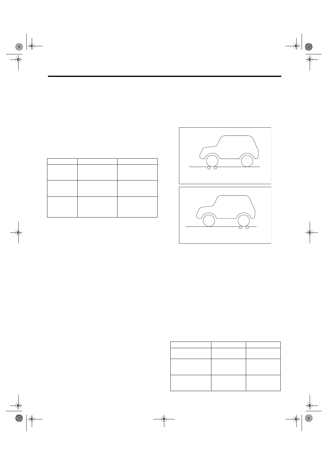
7) Read values indicated on the brake tester and
check if the fluctuation of the values between de-
compression and compression meets specifica-
tion.
Front wheel
Rear wheel
Initial value
3,500 kPa
(36 kgf/cm
2
, 511
psi)
3,500 kPa
(36 kgf/cm
2
, 511
psi)
When depres-
surized
500 kPa
(5 kgf/cm
2
, 73 psi)
or less
500 kPa
(5 kgf/cm
2
, 73 psi)
or less
When pressur-
ized
3,500 kPa
(36 kgf/cm
2
, 511
psi)
or more
3,500 kPa
(36 kgf/cm
2
, 511
psi)
or more
(1) Brake tester
Front wheel
Rear wheel
Initial value
1,000 N
(102 kgf, 225 lbf)
1,000 N
(102 kgf, 225 lbf)
When depressurized
500 N
(51 kgf, 112 lbf)
or less
500 N
(51 kgf, 112 lbf)
or less
When pressurized
1,000 N
(102 kgf, 225 lbf)
or more
1,000 N
(102 kgf, 225 lbf)
or more
ABS00136
(1)
ABS00137
(1)
VDC-11
VDC Control Module and Hydraulic Control Unit (VDCCM&H/U)
VEHICLE DYNAMICS CONTROL (VDC)
8) After the inspection, depress the brake pedal
and check that it is not abnormally hard, and tight-
ness is normal.
3. CHECKING THE HYDRAULIC UNIT VDC
OPERATION USING A PRESSURE GAUGE
1) Lift up the vehicle, and then remove the wheel.
2) Remove the air bleeder screws from FL and FR
caliper bodies.
3) Connect two pressure gauges to FL and FR cal-
iper bodies.
CAUTION:
• Use a pressure gauge used exclusively for
brake fluid measurement.
• Do not use a pressure gauge used for the
measuring transmission oil pressure, as the
piston seal may expand and deform.
NOTE:
Wrap sealing tape around the pressure gauge.
4) Bleed air from the pressure gauge.
5) Perform VDC sequence control. <Ref. to VDC-
6) When the hydraulic unit begins to work, first the
FL side performs compression, hold, and decom-
pression, and then the FR side performs compres-
sion, hold, and decompression.
7) Read values indicated on the pressure gauge
and check if the fluctuation of the values between
decompression and compression meets specifica-
tion. Depress the brake pedal and check that it is
not abnormally hard, and tightness is normal.
8) Disconnect the pressure gauges from FL and FR
caliper bodies.
9) Install the air bleeder screws of FL and FR cali-
per bodies.
10) Remove the air bleeder screws from RL and
RR caliper bodies.
11) Connect two pressure gauges to RL and RR
caliper bodies.
12) Bleed air from RL and RR caliper bodies, and
pressure gauge.
13) Perform VDC sequence control. <Ref. to VDC-
14) When the hydraulic unit begins to work, first the
RR side performs compression, hold, and decom-
pression, and then the RL side performs compres-
sion, hold, and decompression.
15) Read the values indicated on the pressure
gauges and check if it is within specification. De-
press the brake pedal and check that it is not abnor-
mally hard, and tightness is normal.
16) Disconnect the pressure gauge from the RL
and RR caliper bodies.
17) Install the air bleeder screws of RL and RR cal-
iper bodies.
18) Bleed air from the brake system. <Ref. to BR-
4. CHECK HYDRAULIC UNIT VDC OPERA-
TION WITH BRAKE TESTER
1) Set wheels other than the one to measure on
free rollers.
2) Prepare to operate the VDC sequence control.
<Ref. to VDC-17, VDC Sequence Control.>
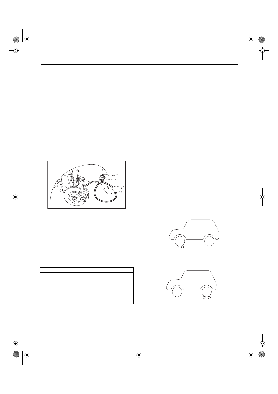
3) Set the front wheels or rear wheels on the brake
tester and set the gear to neutral.
Front wheel
Rear wheel
When pres-
surized
3,000 kPa
(31 kgf/cm
2
, 441
psi)
or more
3,000 kPa
(31 kgf/cm
2
, 441
psi)
or more
When depres-
surized
500 kPa
(5 kgf/cm
2
, 73 psi)
or less
500 kPa
(5 kgf/cm
2
, 73 psi)
or less
ABS00134
(1) Brake tester
ABS00136
(1)
ABS00137
(1)
VDC-12
VDC Control Module and Hydraulic Control Unit (VDCCM&H/U)
VEHICLE DYNAMICS CONTROL (VDC)
4) Operate the brake tester.
5) Perform VDC sequence control. <Ref. to VDC-
6) When the hydraulic unit begins to work, check
the following work sequence.
(1) The FL wheel performs compression, hold
and decompression in sequence, and subse-
quently the FR wheel repeats the cycle.
(2) The RR wheel performs compression, hold
and decompression in sequence, and subse-
quently the RL wheel repeats the cycle.
7) Read values indicated on the brake tester and
check if the fluctuation of the values between de-
compression and compression meets specifica-
tion.
8) After the inspection, depress the brake pedal
and check that it is not abnormally hard, and tight-
ness is normal.
D: REPLACEMENT
CAUTION:
• Because the pressure sensor built into the H/
U is easily damaged by static electricity, start
the operation after performing static electricity
measures.
• Be careful not to touch the sensors in the H/U
to prevent damage.
• Because the seal of the VDCCM cannot be re-
placed, do not pull or peel it by lifting it up.
• Because the screw of the H/U will become
slightly worn in every replacement procedure, 5
times is the maximum number of times for re-
placement. If a problem is found such as not
being able to torque the screw to specifications
even before 5 replacement operations are per-
formed, replace the H/U body.
• When installing the VDCCM, always use new
screws.
• When the sealing surface of the VDCCM or H/
U is dirty or damaged and it cannot be cleaned
or repaired, replace with a new part.
1) Remove the VDCCM&H/U. <Ref. to VDC-8, RE-
MOVAL, VDC Control Module and Hydraulic Con-
2) To prevent entry of foreign objects and brake flu-
id leakage, plug the oil pressure port of the VDC-
CM&H/U using a screw plug, etc.
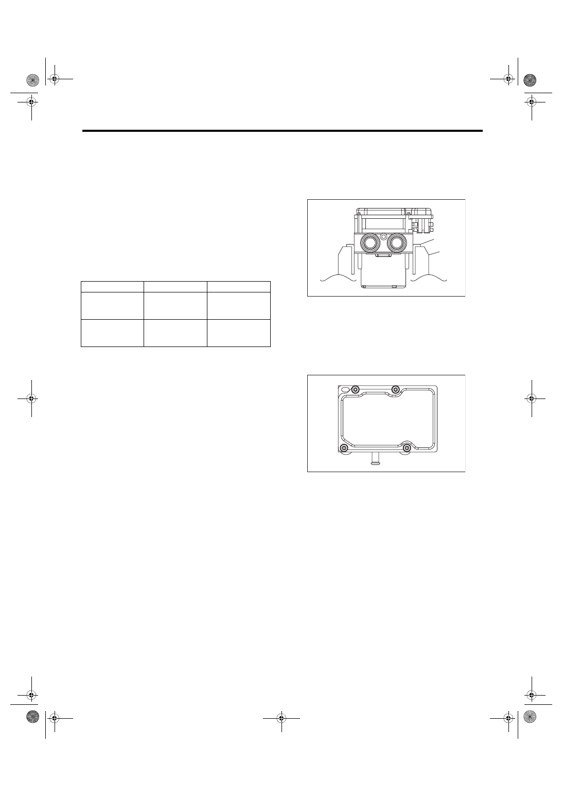
3) Set the pump motor section of the removed VD-
CCM&H/U face down on a vise.
NOTE:
Before securing a part on a vise, place cushioning
material such as wood blocks, aluminum plate, or
cloth between the part and the vise.
4) Using TORX
®
bit E5, remove the four screws of
VDCCM.
NOTE:
Do not re-use the screws.
5) Slowly pull out the VDCCM upward from the H/
U.
NOTE:
To prevent damaging of coil section, remove the
VDCCM straight up from H/U without twisting.
6) Make sure there is no dirt or damage on the seal-
ing surface of the H/U.
CAUTION:
• Do not clean the VDCCM&H/U by applying
compressed air.
• Even if damage is found on the H/U seal, do
not attempt repair by filing or with a metal
scraper. To remove the seal residue, always
use a plastic scraper. Do not use chemical such
as paint thinner, etc., to clean.
7) Position the coil of the new VDCCM to align with
the H/U valve.
8) To prevent deformation of the VDCCM housing
cover, hold the corner of VDCCM and install it to
the H/U without tilting.
Front wheel
Rear wheel
When pressurized
2,000 N
(204 kgf, 450 lbf)
or more
2,000 N
(204 kgf, 450 lbf)
or more
When depressur-
ized
500 N
(51 kgf, 112 lbf)
or less
500 N
(51 kgf, 112 lbf)
or less
(1) Aluminum plate, etc.
(2) Vise
ABS00430
(1)
(2)
ABS00431
Нет комментариевНе стесняйтесь поделиться с нами вашим ценным мнением.
Текст