Subaru Impreza 3 / Impreza WRX / Impreza WRX STI. Service manual — part 519
VDC-5
General Description
VEHICLE DYNAMICS CONTROL (VDC)
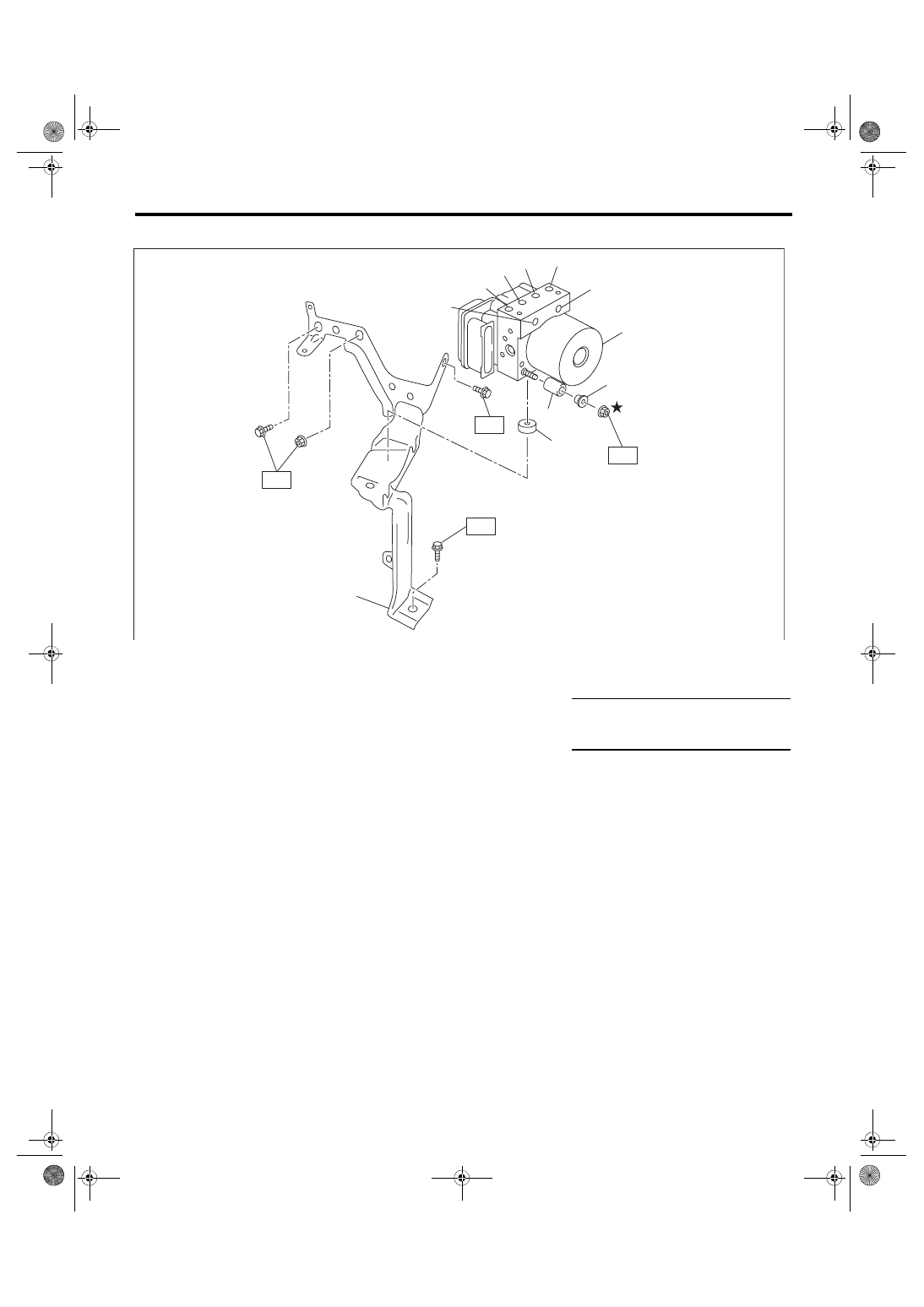
4. VDC CONTROL MODULE & HYDRAULIC CONTROL UNIT (VDCCM&H/U)
(1)
VDC control module and hydraulic
control unit (VDCCM&H/U)
(6)
Primary inlet
(11) Bracket
(2)
Front RH outlet
(7)
Secondary inlet
(3)
Rear LH outlet
(8)
Damper
Tightening torque: N·m (kgf-m, ft-lb)
(4)
Rear RH outlet
(9)
Spacer
T1: 7.5 (0.76, 5.5)
(5)
Front LH outlet
(10) Damper
T2: 33 (3.36, 24.3)
VDC00480
(1)
(8)
(7)
(6)
(5)
(4)
(3)
(10)
(2)
T1
T2
(11)
(9)
T2
T2
VDC-6
General Description
VEHICLE DYNAMICS CONTROL (VDC)
C: CAUTION
• Wear appropriate work clothing, including a helmet, protective goggles and protective shoes when per-
forming any work.
• Remove contamination including dirt and corrosion before removal, installation or disassembly.
• Keep the disassembled parts in order and protect them from dust and dirt.
• Before disconnecting connectors of sensors or units, be sure to disconnect the ground cable from battery.
• Before removal, installation or disassembly, be sure to clarify the failure. Avoid unnecessary removal, in-
stallation, disassembly and replacement.
• Vehicle components are extremely hot after driving. Be wary of receiving burns from heated parts.
• Be sure to tighten fasteners including bolts and nuts to the specified torque.
• Place shop jacks or rigid racks at the specified points.
D: PREPARATION TOOL
1. SPECIAL TOOL
2. GENERAL TOOL
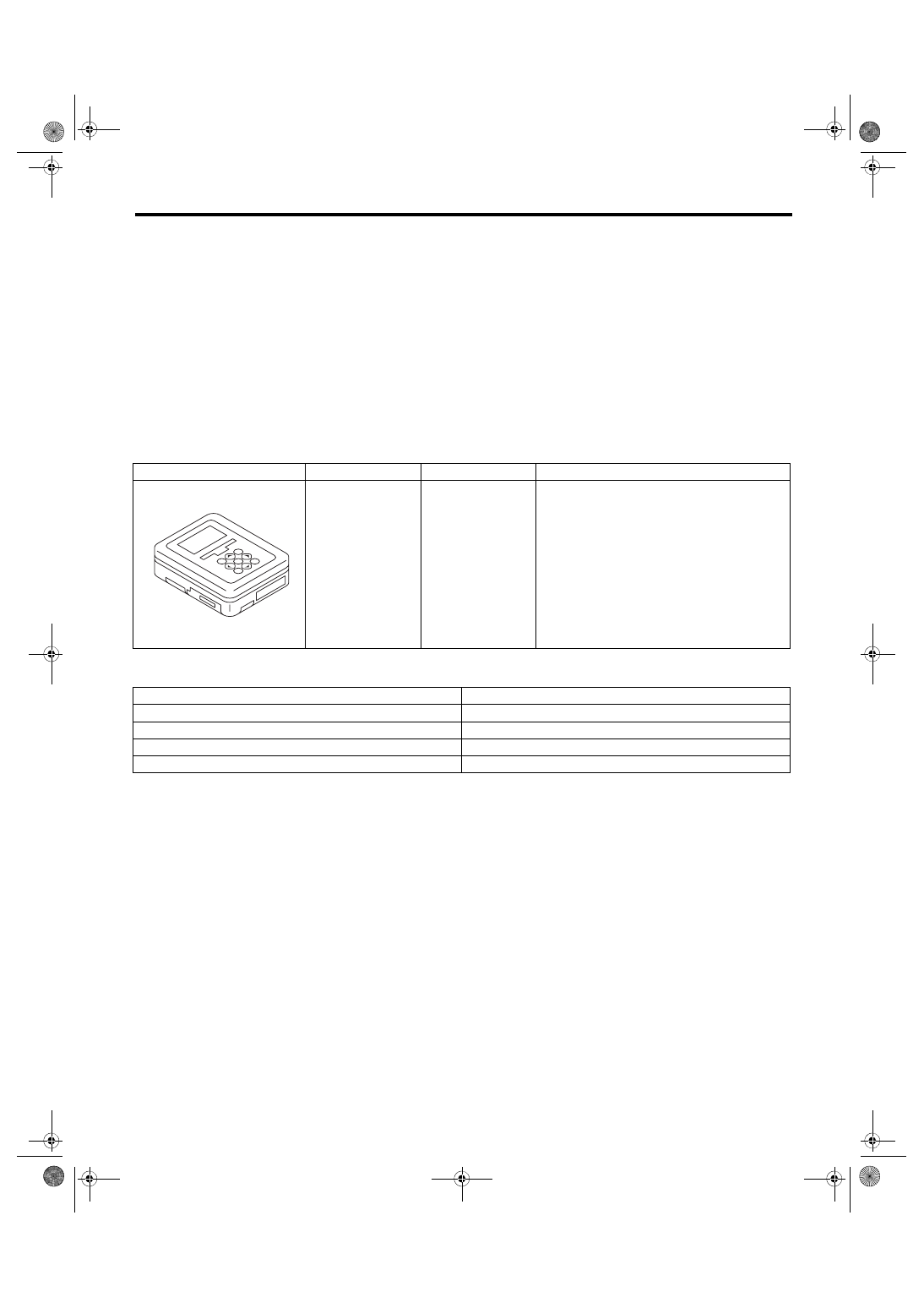
ILLUSTRATION
TOOL NUMBER
DESCRIPTION
REMARKS
1B022XU0
SUBARU SELECT
MONITOR III KIT
Used for troubleshooting the electrical system.
TOOL NAME
REMARKS
Circuit tester
Used for measuring resistance and voltage.
Pressure gauge
Used for measuring oil pressure.
Oscilloscope
Used for measuring the sensor.
TORX
®
bit E5
Used for replacing VDC control module.
ST1B022XU0
VDC-7
Vehicle Dynamics Control System
VEHICLE DYNAMICS CONTROL (VDC)
2. Vehicle Dynamics Control System
A: WIRING DIAGRAM
hicle Dynamics Control System.>
B: ELECTRICAL SPECIFICATION
Refer to the Control Module I/O Signal of the “Vehicle Dynamics Control System (VDC) (DIAGNOSTICS)”.
<Ref. to VDC(diag)-14, ELECTRICAL SPECIFICATION, Control Module I/O Signal.>
C: INSPECTION
Refer to the “Vehicle Dynamics Control System (VDC) (DIAGNOSTICS)”. <Ref. to VDC(diag)-110, INSPEC-
TION, General Diagnostic Table.>
D: NOTE
For operation procedures of each component of the vehicle dynamics control system, refer to the respective
section.
draulic Control Unit (VDCCM&H/U).>
• Yaw rate & G sensor: <Ref. to VDC-20, Yaw Rate and G Sensor.>
• Steering angle sensor: <Ref. to VDC-22, Steering Angle Sensor.>
• Front ABS wheel speed sensor: <Ref. to VDC-24, Front ABS Wheel Speed Sensor.>
• Rear ABS wheel speed sensor: <Ref. to VDC-26, Rear ABS Wheel Speed Sensor.>
• Front magnetic encoder: <Ref. to VDC-27, Front Magnetic Encoder.>
• Rear magnetic encoder: <Ref. to VDC-28, Rear Magnetic Encoder.>
VDC-8
VDC Control Module and Hydraulic Control Unit (VDCCM&H/U)
VEHICLE DYNAMICS CONTROL (VDC)
3. VDC Control Module and Hy-
draulic Control Unit (VDC-
CM&H/U)
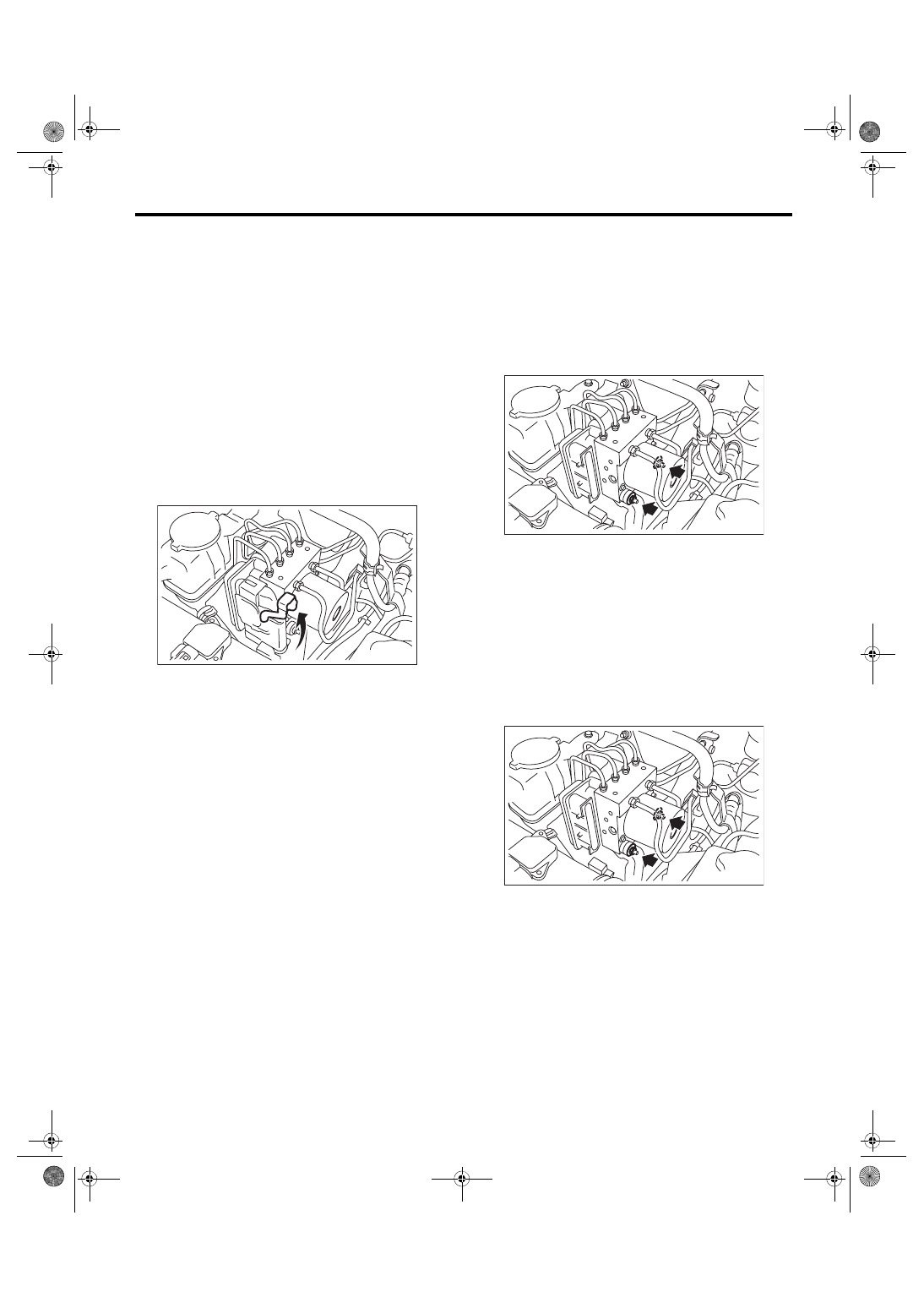
A: REMOVAL
1) Disconnect the ground cable from battery.
2) Use compressed air to remove moisture and
dust around the VDCCM&H/U.
NOTE:
If the terminals become dirty, it may cause improp-
er contact.
3) Lift the lock lever and Disconnect the VDC-
CM&H/U connector.
CAUTION:
Do not pull on the harness when disconnecting
the connector.
4) Disconnect the brake pipes from the VDC-
CM&H/U.
5) Wrap the brake pipe with a vinyl bag so as not to
spill the brake fluid on the vehicle body.
CAUTION:
If brake fluid is spilled on the painted surface of
the vehicle body, wash it off immediately with
water and wipe clean.
6) Remove the nuts and remove the VDCCM&H/U.
CAUTION:
• Do not drop or bump the VDCCM&H/U.
• Do not turn the VDCCM&H/U upside down or
place it sideways for storage.
• Be careful not to let foreign matter enter the
VDCCM&H/U.
• Be careful that no water enters the connec-
tors.
7) Remove the VDCCM&H/U bracket.
B: INSTALLATION
1) Install the VDCCM&H/U bracket.
Tightening torque:
33 N·m (3.36 kgf-m, 24.3 ft-lb)
2) Install the VDCCM&H/U with a new nut by align-
ing the damper groove of the VDCCM&H/U to the
bracket side claw.
Tightening torque:
7.5 N·m (0.76 kgf-m, 5.5 ft-lb)
VDC00449
VDC00450
VDC00450
Нет комментариевНе стесняйтесь поделиться с нами вашим ценным мнением.
Текст