Subaru Impreza 3 / Impreza WRX / Impreza WRX STI. Service manual — part 435
6MT-77
Main Shaft Assembly
MANUAL TRANSMISSION AND DIFFERENTIAL
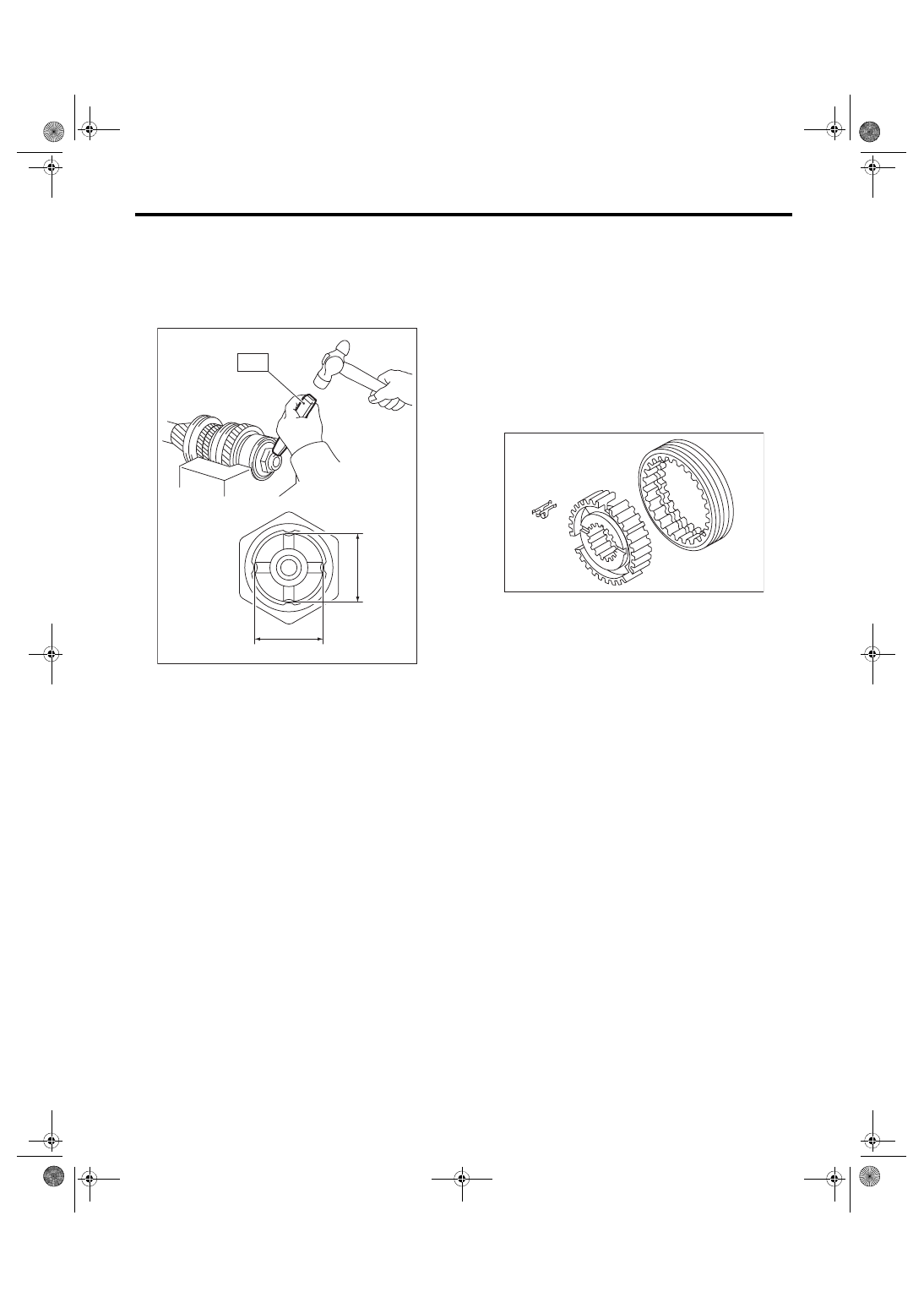
32) Using the ST, crimp the lock nut in 4 locations,
with dimensions within A 27±0.3 mm (1.06±0.01
in).
ST 18668AA000 PUNCH
NOTE:
Do not damage the crimp area of the lock nut.
E: INSPECTION
Disassembled parts should be washed with clean-
ing solvent first, then inspected carefully.
1) Bearing
Replace the bearings in the following cases.
• Wear, rusting or damage of the bearings
• The bearing does not rotate smoothly or an ab-
normal noise is emitted when turning.
• The bearing has other defects.
2) Bushing (each gear)
Replace the bushing in following cases.
• The sliding surface is damaged or abnormally
worn.
3) Gear
Replace gears in the following cases.
• The gear teeth surface is damaged or excessive-
ly worn.
• The contact area of the baulk ring is damaged.
• The inner face of the gear is worn.
4) Baulk ring, synchro cone
Replace the baulk ring and synchro cone in the fol-
lowing cases.
• Wear, rusting or damage of the baulk ring
5) Shifting insert key
Replace the shifting insert key if deformed, exces-
sively worn or defective in any way.
F: ADJUSTMENT
1. MAIN SHAFT SNAP RING & ADJUSTING
WASHER SELECTION
NOTE:
In the following conditions, perform the procedures
below.
• 1st to 6th driven gear replacement
• 1st and 2nd synchro ring assembly replacement
• Ball bearing replacement
• Adapter plate replacement
• Driven shaft replacement
1) Insert the drive pinion assembly into the adapter
plate.
NOTE:
Confirm that the thrust bearing outer race has not
been removed and the drive pinion is not lifted.
MT-00580
A
A
ST
MT-00581
6MT-78
Main Shaft Assembly
MANUAL TRANSMISSION AND DIFFERENTIAL
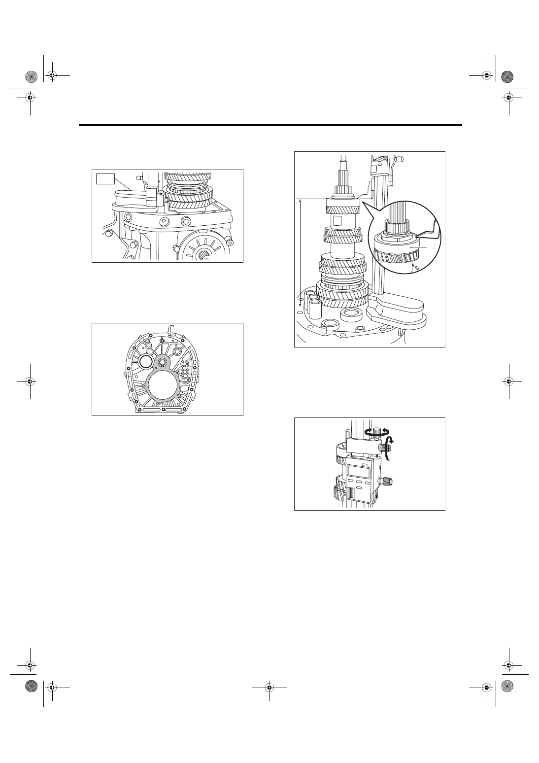
2) Set the height gauge to the adapter plate. Lower
the height gauge indicator to the mating surface of
the adapter plate and case, and set to zero points.
ST 18853AA000 HEIGHT GAUGE
NOTE:
• The adapter plate will be the base point for the
measurement. Use a scraper to remove any gasket
material remaining on the end face.
• During measurement, do not place the height
gauge in the shaded area shown in the figure.
3) Measure the height to the ball bearing end face
(height H).
NOTE:
Set the height gauge indicator near the measure-
ment target, and lock dial (1) as shown in the figure.
Turn dial (2), and set the indicator to the end face of
the bearing.
Turn approximately 120° at a time, and measure
the ball bearing in 5 locations. Round down the 2
highest and 2 lowest measurement values. The re-
maining center value is used as the measurement
value.
MT-00582
ST
MT-00583
(A) Ball bearing
(A)
MT-00955
H
MT-00585
(2)
(1)
6MT-79
Main Shaft Assembly
MANUAL TRANSMISSION AND DIFFERENTIAL
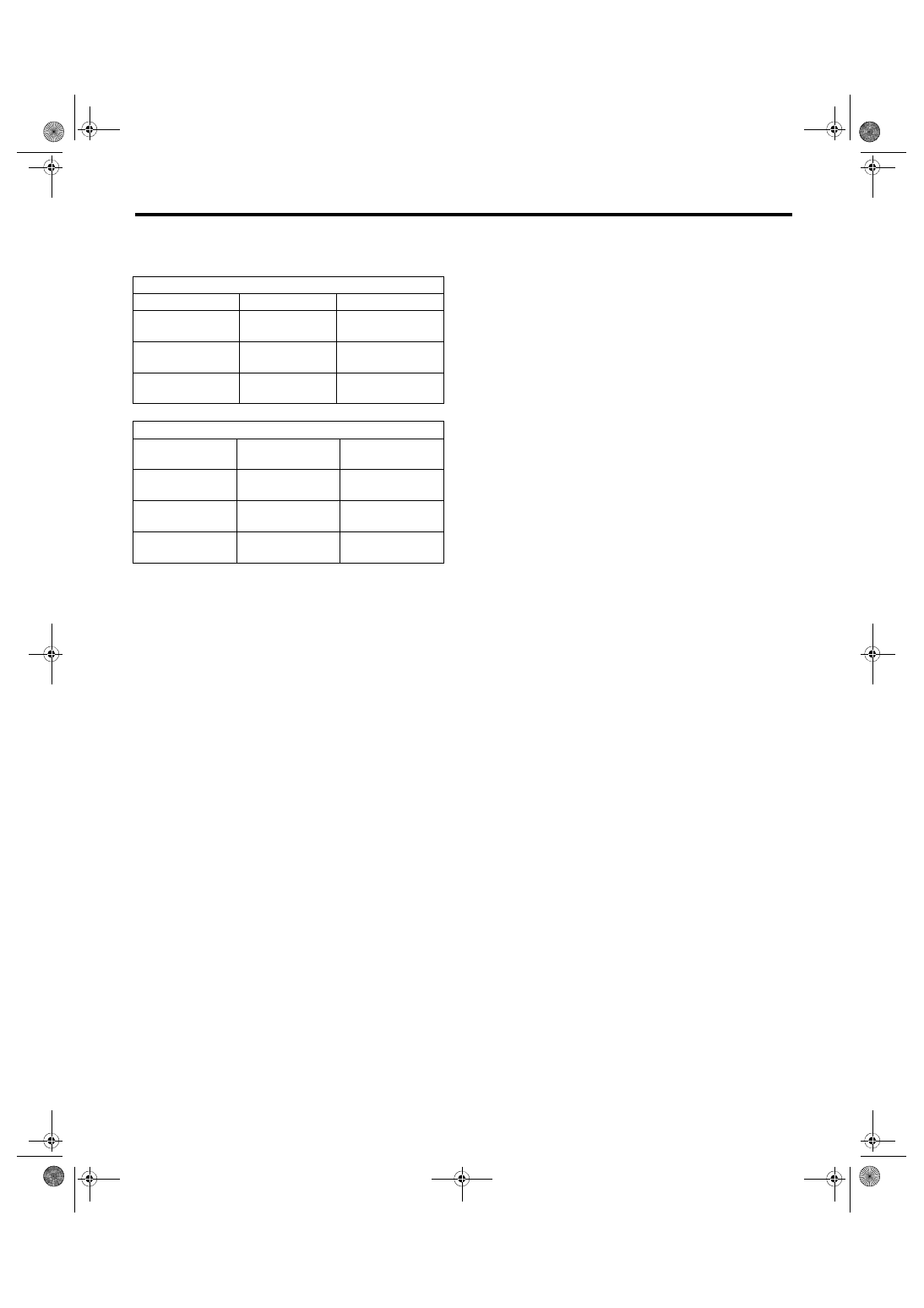
4) According to the measurement value, select the
snap ring and adjusting washer from the following
table.
Snap ring
H: mm (in)
Part No.
Thickness: mm (in)
270.83 — 271.40
(10.66 — 10.69)
805072010
1.65
(0.065)
271.41 — 271.98
(10.69 — 10.71)
805072011
1.95
(0.077)
271.99 — 272.56
(10.71 — 10.73)
805072012
2.25
(0.089)
Adjusting washer
H: mm (in)
Part No.
Thickness: mm
(in)
270.83 — 271.40
(10.66 — 10.69)
803067012
1.6
(0.063)
271.41 — 271.98
(10.69 — 10.71)
803067011
1.3
(0.051)
271.99 — 272.56
(10.71 — 10.73)
803067010
1.0
(0.039)
6MT-80
Driven Gear Assembly
MANUAL TRANSMISSION AND DIFFERENTIAL
18.Driven Gear Assembly
A: REMOVAL
1) Remove the manual transmission assembly
from the vehicle. <Ref. to 6MT-31, REMOVAL,
Manual Transmission Assembly.>
2) Prepare the transmission for overhaul. <Ref. to
6MT-37, Preparation for Overhaul.>
3) Remove the neutral position switch, back-up
light switch and harness. <Ref. to 6MT-41, RE-
MOVAL, Neutral Position Switch.> <Ref. to 6MT-
39, REMOVAL, Back-up Light Switch.>
4) Remove the extension case. <Ref. to 6MT-43,
5) Remove the transfer driven gear. <Ref. to 6MT-
55, REMOVAL, Transfer Driven Gear.>
6) Remove the center differential. <Ref. to 6MT-57,
REMOVAL, Center Differential.>
7) Remove the transmission case. <Ref. to 6MT-
58, REMOVAL, Transmission Case.>
8) Remove the driven gear assembly. <Ref. to
6MT-65, REMOVAL, Main Shaft Assembly.>
9) Remove the 1st needle bearing.
10) Remove the thrust needle bearing.
B: INSTALLATION
1) Adjust the main shaft snap ring. <Ref. to 6MT-
77, ADJUSTMENT, Main Shaft Assembly.>
2) Adjust the 1st-2nd shifter rod. <Ref. to 6MT-112,
ADJUSTMENT, Shifter Fork and Rod.>
3) Install the thrust needle bearing.
NOTE:
Confirm that the thrust needle bearing is installed in
the proper direction.
4) Install the 1st needle bearing.
5) Install the driven gear assembly. <Ref. to 6MT-
66, INSTALLATION, Main Shaft Assembly.>
6) Install the transmission case. <Ref. to 6MT-60,
INSTALLATION, Transmission Case.>
7) Adjust the backlash of the driven gear assembly
in the axial direction. <Ref. to 6MT-88, ADJUST-
8) Install the center differential. <Ref. to 6MT-57,
INSTALLATION, Center Differential.>
9) Install the transfer driven gear. <Ref. to 6MT-55,
INSTALLATION, Transfer Driven Gear.>
10) Install the extension case. <Ref. to 6MT-43, IN-
11) Install the neutral position switch, back-up light
switch and harness. <Ref. to 6MT-41, INSTALLA-
TION, Neutral Position Switch.> <Ref. to 6MT-39,
INSTALLATION, Back-up Light Switch.>
12) Install the manual transmission assembly to the
vehicle. <Ref. to 6MT-33, INSTALLATION, Manual
C: DISASSEMBLY
NOTE:
Individual sleeves and hubs meet at a specified po-
sition. Before disassembly, mark the meeting posi-
tion of the sleeve and hub.
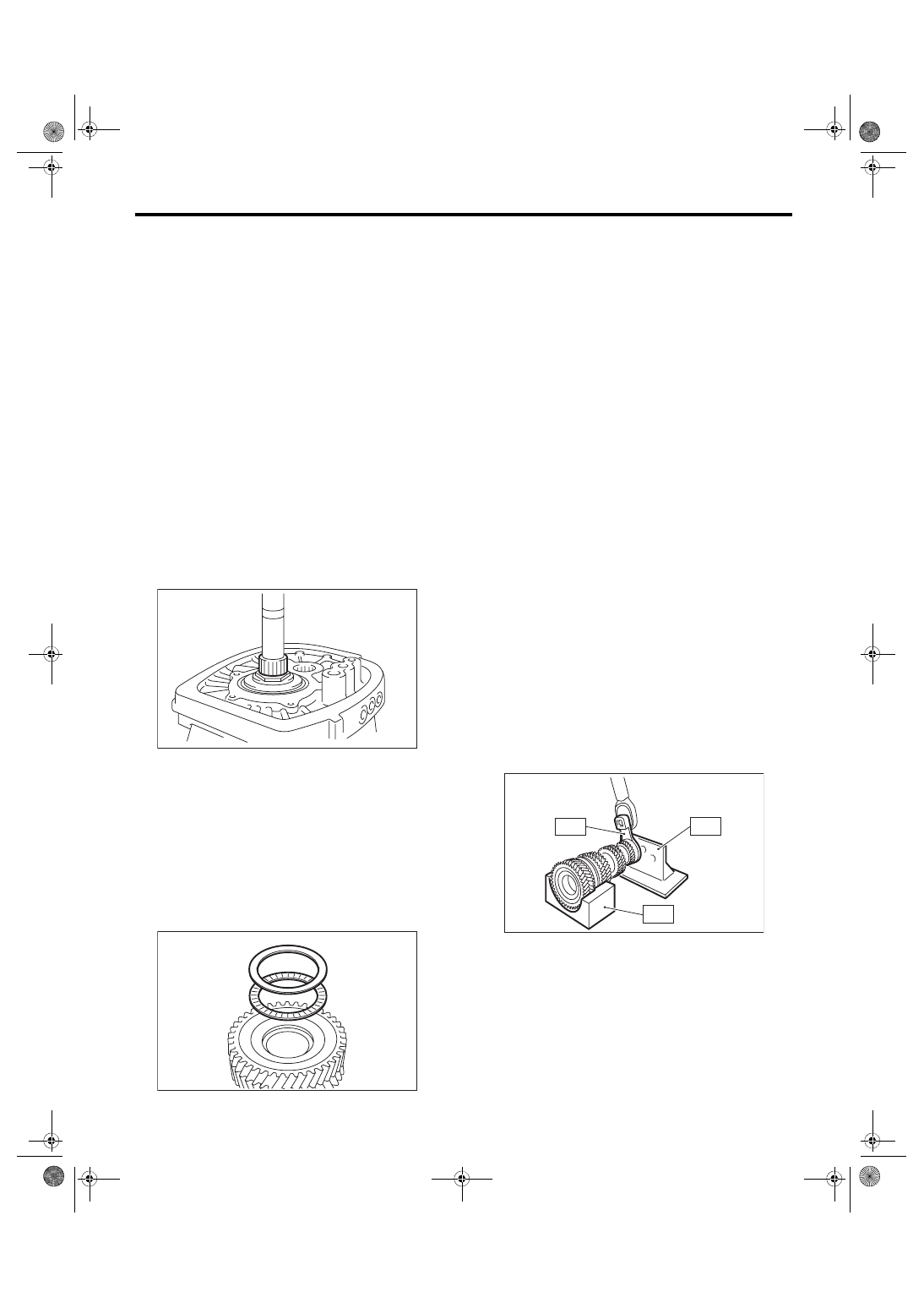
1) Affix the ST to the work table.
ST 18664AA000
BASE
2) Flatten the tab of the lock nut.
3) Attach ST3 to the lock nut, set the driven gear
assembly to the ST, and remove the lock nut.
ST1 18666AA000
HOLDER
ST2 18664AA000
BASE
ST3 18620AA000
ADAPTER WRENCH
MT-00586
MT-00587
MT-00588
ST3
ST2
ST1
Нет комментариевНе стесняйтесь поделиться с нами вашим ценным мнением.
Текст