Subaru Impreza 3 / Impreza WRX / Impreza WRX STI. Service manual — part 408
5MT-53
Main Shaft Assembly for Single-Range
MANUAL TRANSMISSION AND DIFFERENTIAL
15.Main Shaft Assembly for Sin-
gle-Range
A: REMOVAL
1) Remove the manual transmission assembly
from the vehicle. <Ref. to 5MT-23, REMOVAL,
Manual Transmission Assembly.>
2) Remove the transfer case together with the ex-
tension case assembly. <Ref. to 5MT-35, REMOV-
AL, Transfer Case and Extension Case
3) Remove the transmission case. <Ref. to 5MT-
49, REMOVAL, Transmission Case.>
4) Remove the drive pinion shaft assembly. <Ref.
to 5MT-58, REMOVAL, Drive Pinion Shaft Assem-
5) Remove the main shaft assembly for single-
range.
B: INSTALLATION
1) Install the needle bearing and oil seal to the front
of the transmission single-range main shaft assem-
bly.
NOTE:
• Wrap the clutch splined section with vinyl tape to
prevent damage to the oil seal.
• Apply NICHIMOLY N-130 or the equivalent to
the sealing lip of the oil seal.
• Use a new oil seal.
2) Align the transmission case knock pin into the
knock pin hole of the needle bearing outer race.
NOTE:
Align the end face of the seal with surface (A) when
installing the oil seal.
3) Install the drive pinion shaft assembly. <Ref. to
5MT-58, INSTALLATION, Drive Pinion Shaft As-
4) Install the transmission case. <Ref. to 5MT-50,
INSTALLATION, Transmission Case.>
5) Install the transfer case together with the exten-
sion case assembly. <Ref. to 5MT-35, INSTALLA-
TION, Transfer Case and Extension Case
6) Install the manual transmission assembly to the
vehicle. <Ref. to 5MT-26, INSTALLATION, Manual
C: DISASSEMBLY
1) Put vinyl tape around main shaft spline to protect
the oil seal from damage. Then pull out the oil seal
and needle bearing by hand.
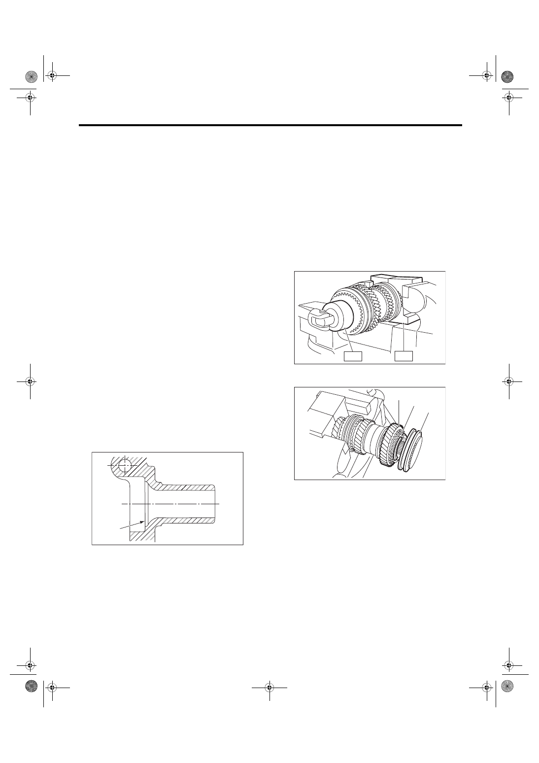
2) Remove the lock nut and lock washer from
transmission main shaft assembly for single-range.
NOTE:
Flatten the lock nut tab before removing the lock
nut.
ST1 498937000
TRANSMISSION HOLDER
ST2 499987003
SOCKET WRENCH (35)
3) Remove the 5th hub & sleeve No. 2, baulk lever,
baulk ring, 5th drive gear and needle bearing.
MT-00185
(A)
(A) 5th hub & sleeve No. 2
(B) Baulk ring
(C) 5th drive gear
ST2
ST1
MT-01517
( A )
( B )
( C )
MT-01518
5MT-54
Main Shaft Assembly for Single-Range
MANUAL TRANSMISSION AND DIFFERENTIAL
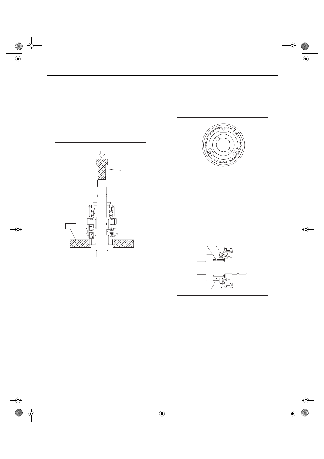
4) Using ST1 and ST2, remove the rest of the
parts.
NOTE:
• When replacing the sleeve & hub, replace them
as a set.
• Do not disassemble the sleeve & hub; the align-
ing position is pre-matched.
• If it is necessary to disassemble, mark the en-
gaging points on the splines beforehand.
ST1 899864100
REMOVER
ST2 899714110
REMOVER
D: ASSEMBLY
1) When the sleeve & hub assemblies have been
disassembled, reassemble by aligning the align-
ment marks.
NOTE:
Position the open ends of the spring 120° apart.
2) Install the 3rd drive gear, outer baulk ring, syn-
chro cone, inner baulk ring, sleeve & hub assembly
for the 3rd needle bearing, on the transmission
main shaft.
NOTE:
Align the groove in baulk ring with the shifting in-
sert.
(A) Press
MT-00190
(A)
ST2
ST1
(A) 3rd-4th coupling sleeve & synchronizer hub
ASSY
(B) 3rd gear side
(A) 3rd needle bearing
(B) 3rd drive gear
(C) Inner baulk ring
(D) Synchro cone
(E) Outer baulk ring
(F) Sleeve & hub ASSY
MT-01852
(A)
(B)
MT-01318
(A)
(B)
(C)
(D)
(E)
(F)
5MT-55
Main Shaft Assembly for Single-Range
MANUAL TRANSMISSION AND DIFFERENTIAL
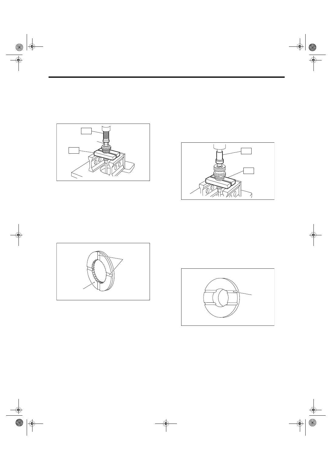
3) Install the 4th needle bearing race onto trans-
mission main shaft using ST1, ST2 and press.
CAUTION:
Do not apply a load in excess of 10 kN (1 ton, 1.1
US ton, 1.0 Imp ton).
ST1 899714110
REMOVER
ST2 499877000
RACE 4-5 INSTALLER
4) Install the baulk ring, needle bearing, 4th drive
gear and 4th gear thrust washer to the transmission
main shaft.
NOTE:
• Align the baulk ring and hub & sleeve assembly
with the key groove.
• Make sure the thrust washer is facing the correct
direction.
5) Press-fit the double taper roller bearing into the
rear section of transmission main shaft using ST1,
ST2 and a press.
CAUTION:
Do not apply a load in excess of 10 kN (1 ton, 1.1
US ton, 1.0 Imp ton).
NOTE:
Use a new double taper roller bearing.
ST1 899714110
REMOVER
ST2 499877000
RACE 4-5 INSTALLER
6) Install the 5th needle bearing race into the rear
section of transmission main shaft using ST1 and
ST2.
CAUTION:
Do not apply a load in excess of 10 kN (1 ton,
1.1 US ton, 1.0 Imp ton).
NOTE:
Make sure the thrust washer is facing the correct
direction.
ST1 899714110
REMOVER
ST2 499877000
RACE 4-5 INSTALLER
(A) 4th needle bearing race
(A) Groove
(B) Face this surface to the 4th gear side.
MT-00192
(A)
ST1
ST2
MT-02132
(A)
(B)
(A) Face this surface to the 5th gear side.
MT-00194
ST1
ST2
MT-00195
(A)
5MT-56
Main Shaft Assembly for Single-Range
MANUAL TRANSMISSION AND DIFFERENTIAL
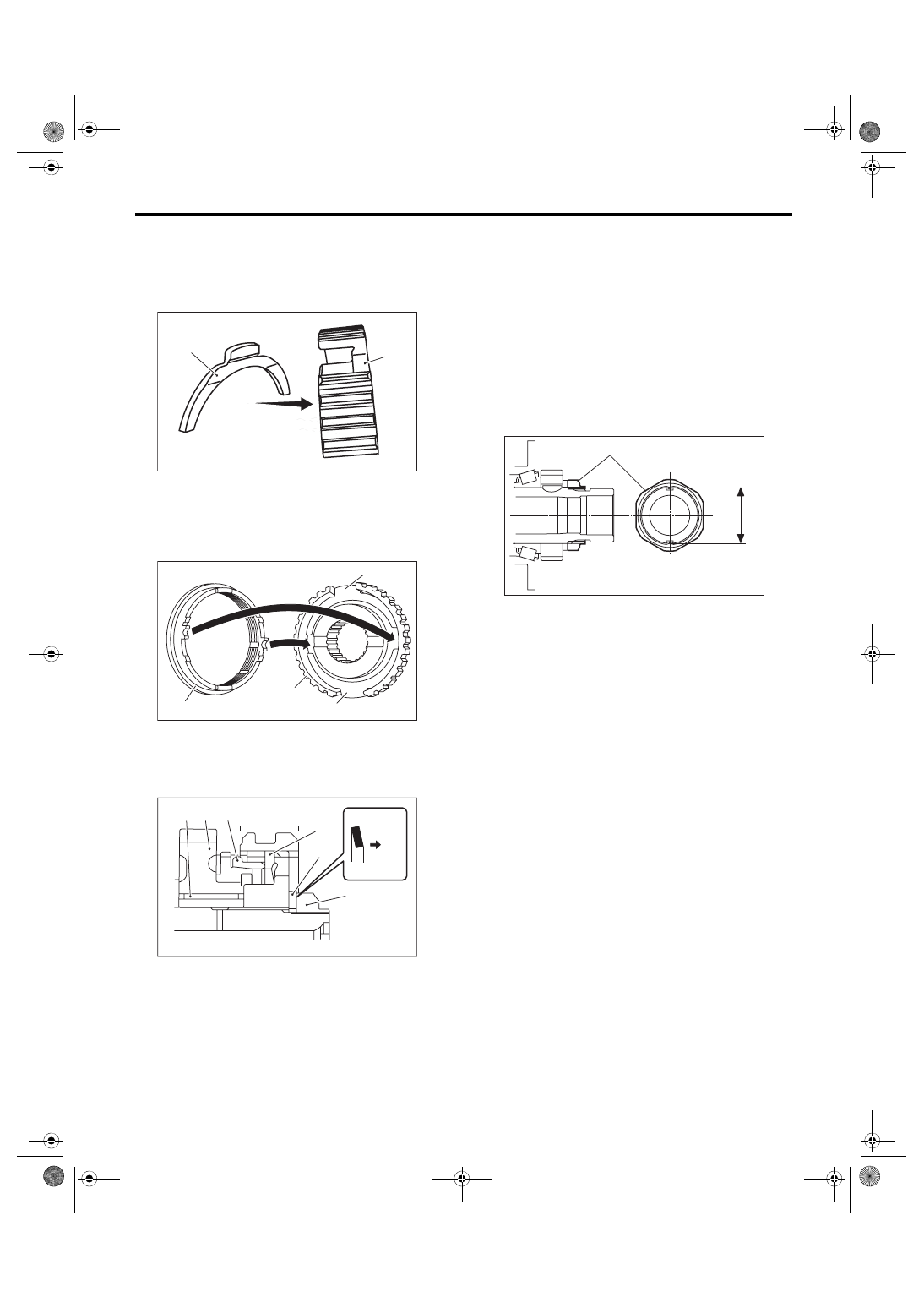
7) Install rest of the parts to the rear section of the
transmission main shaft.
CAUTION:
• Install the baulk lever so that the concave
side faces toward the 5th hub.
• Align the protruded section of baulk ring be-
tween the baulk levers.
8) Tighten the lock nuts to the specified torque us-
ing ST1 and ST2.
NOTE:
Use new lock nuts and lock washers.
ST1 499987003
SOCKET WRENCH (35)
ST2 498937000
TRANSMISSION HOLDER
Tightening torque:
120 N·m (12.2 kgf-m, 88.5 ft-lb)
9) Crimp lock nuts in two locations after tightening.
CAUTION:
When crimping the lock nut, be careful not to
crack it.
E: INSPECTION
Disassembled parts should be washed with clean-
ing solvent first, then inspected carefully.
1) Bearing
Replace the bearings in the following cases.
• When the bearing balls, outer races and inner
races are broken or rusty.
• When the bearing is worn.
• When the bearings fail to turn smoothly or emit
noise in rotation after gear oil lubrication.
• When bearing has other defects.
2) Bushing (each gear)
Replace the bushing in following cases.
• When the sliding surface is damaged or abnor-
mally worn.
• When the inner wall is abnormally worn.
3) Gear
Replace gears in the following cases.
• Replace the gear with new part if its tooth surfac-
es are broken, damaged or excessively worn.
• Correct or replace if the cone that contacts the
baulk ring is rough or damaged.
• Correct or replace if the inner surface or end face
is damaged.
4) Baulk ring
Replace the baulk ring in the following cases.
• When the inner surface and end face are dam-
aged.
(A) Baulk lever
(B) 5th hub
(A) Baulk ring
(B) Baulk lever
(C) 5th hub
(A) Needle bearing
(B) 5th drive gear
(C) Baulk ring
(D) 5th hub & sleeve No. 2
(E) Lock washer
(F) Lock nut
(G) Baulk lever
(H) Nut side
(A)
(B)
MT-01522
MT-01531
(A)
(B)
(C)
(B)
MT-02771
(D)
(A) (B) (C)
(E)
(F)
(G)
(H)
(A) Lock nut
(B) Outer dimension after crimping
(B)
(A)
MT-02707
Нет комментариевНе стесняйтесь поделиться с нами вашим ценным мнением.
Текст