Subaru Impreza 3 / Impreza WRX / Impreza WRX STI. Service manual — part 551
VDC(diag)-103
Diagnostic Procedure with Diagnostic Trouble Code (DTC)
VEHICLE DYNAMICS CONTROL (VDC) (DIAGNOSTICS)
AX:DTC C0074 PRESSURE SENSOR
DTC DETECTING CONDITION:
Defective pressure sensor
TROUBLE SYMPTOM:
• ABS does not operate.
• VDC does not operate.
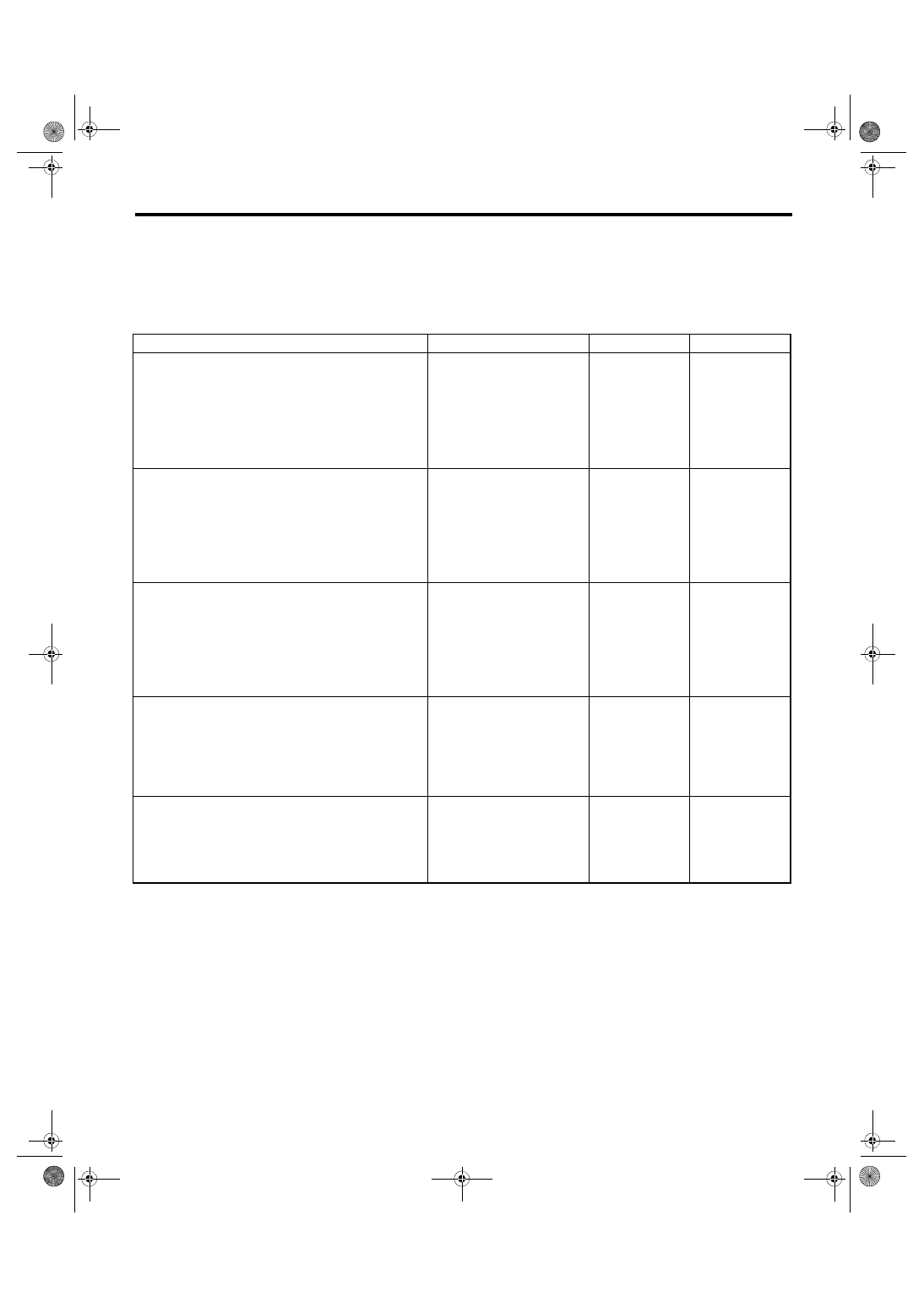
Step
Check
Yes
No
1
CHECK STOP LIGHT SWITCH CIRCUIT.
Check stop light switch open circuit.
Is the stop light switch circuit
OK?
Repair the stop
light switch circuit.
NOTE:
If there is malfunc-
tion in the stop light
circuit, DTC may
be recorded in the
memory.
2
CHECK OUTPUT OF PRESSURE SENSOR
WITH SUBARU SELECT MONITOR.
1) Select “Current Data Display & Save” in
Subaru Select Monitor. <Ref. to VDC(diag)-19,
READ CURRENT DATA, OPERATION, Subaru
Select Monitor.>
2) Read the «Pressure Sensor Output» dis-
played on display.
When the brake pedal is
released, is the displayed value
–40 — 40 bar?
Replace the
VDCCM&H/U.
<Ref. to VDC-8,
VDC Control Mod-
ule and Hydraulic
Control Unit
(VDCCM&H/U).>
3
CHECK OUTPUT OF PRESSURE SENSOR
WITH SUBARU SELECT MONITOR.
1) Select “Current Data Display & Save” in
Subaru Select Monitor. <Ref. to VDC(diag)-19,
READ CURRENT DATA, OPERATION, Subaru
Select Monitor.>
2) Read the «Pressure Sensor Output» dis-
played on display.
When the brake pedal is oper-
ated, does the pressure sensor
output value displayed on the
screen change in accordance
with the brake pedal?
Replace the
VDCCM&H/U.
<Ref. to VDC-8,
VDC Control Mod-
ule and Hydraulic
Control Unit
(VDCCM&H/U).>
4
CHECK PRESSURE SENSOR.
1) Clear the memory. <Ref. to VDC(diag)-27,
Clear Memory Mode.>
2) Perform the Inspection Mode. <Ref. to
VDC(diag)-26, Inspection Mode.>
3) Read the DTC.
Is the same DTC displayed?
Replace the
VDCCM&H/U.
<Ref. to VDC-8,
VDC Control Mod-
ule and Hydraulic
Control Unit
(VDCCM&H/U).>
5
CHECK OTHER DTC DETECTION.
Is any other DTC displayed?
It results from a
temporary noise
interference.
VDC(diag)-104
Diagnostic Procedure with Diagnostic Trouble Code (DTC)
VEHICLE DYNAMICS CONTROL (VDC) (DIAGNOSTICS)
AY:DTC C0075 REVERSE SIGNAL
DTC DETECTING CONDITION:
Abnormal reverse signal
TROUBLE SYMPTOM:
Hill start assist does not operate.
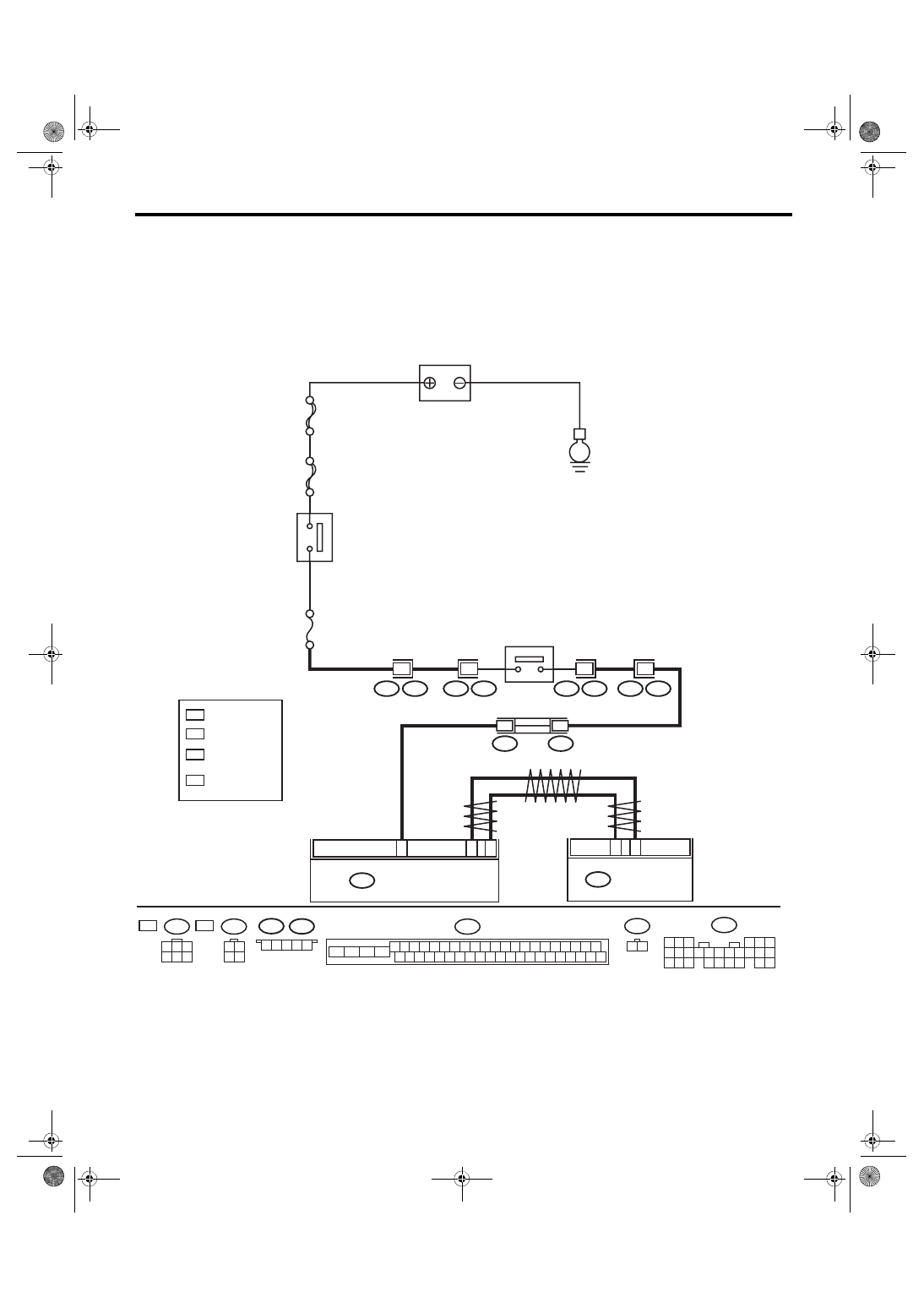
WIRING DIAGRAM:
Back-up light system <Ref. to WI-95, Back-up Light System.>
VDC00890
B280
B:
B1
8
B3
B9
B434
B436
B310
35
10
T13
T1
T1
T13
T9
T9
B128
B128
*
2
1
B436
B434
2
*
1
6M
B128
3 4
1 2
*
2
5M
6M
5M
*
1
2
6
5
4
3
1
5
5
26
25
24
23
22
21
20
19
18
17
16
15
14
13
12
11
10
9
8
7
6
5
4
3
2
1
B: B280
2
1
T1
B128
25
22
24
23
21
20
46
45
44
43
42
41
13
12
40
39
38
37
19
18
17
16
15
14
11
10
36
35
34
33
32
31
1
3
2
30
29
28
27
26
9
8
7
6
5
4
B310
5
4
3
2
1
E
:
:
SBF-
8
: 6MT MODEL
: 5MT MODEL
: 5MT MODEL : 2
6MT MODEL : 3
VDCCM & H/U
BACK-UP
LIGHT SWITCH
IG 2 RELAY
BATTERY
BODY INTEGRATED UNIT
No.
1
8
MAIN SBF
: 5MT MODEL : 4
6MT MODEL : 6
VDC(diag)-105
Diagnostic Procedure with Diagnostic Trouble Code (DTC)
VEHICLE DYNAMICS CONTROL (VDC) (DIAGNOSTICS)
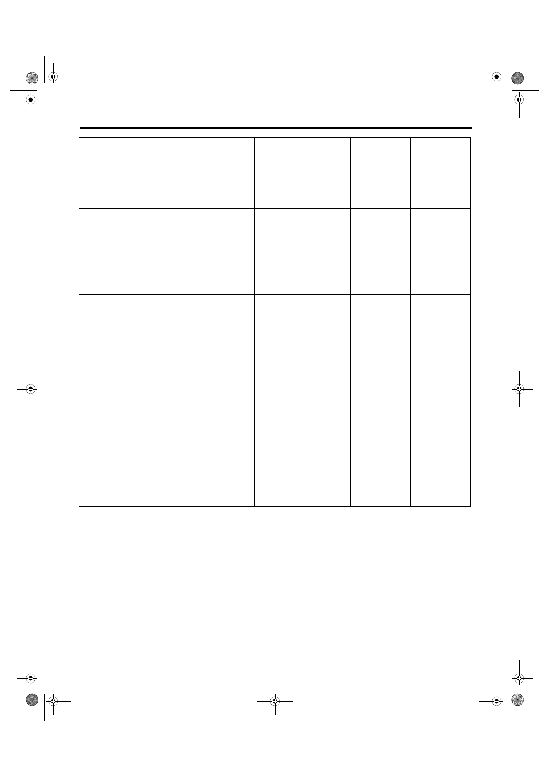
Step
Check
Yes
No
1
CHECK LAN SYSTEM.
Perform the diagnosis for LAN system. <Ref. to
LAN(diag)-2, Basic Diagnostic Procedure.>
Is there any fault in LAN sys-
tem?
2
CHECK REVERSE SIGNAL USING SUBARU
SELECT MONITOR.
1) Select “Current Data Display & Save” on the
Subaru Select Monitor. <Ref. to VDC(diag)-19,
READ CURRENT DATA, OPERATION, Subaru
Select Monitor.>
2) Read the «Reverse Signal».
Is “OFF” displayed when the
shift lever is placed in any posi-
tion other than reverse, and is
“ON” displayed in reverse posi-
tion?
3
CHECK BACK-UP LIGHT ILLUMINATION.
1) Turn the ignition switch to ON.
2) Place the shift lever in reverse position.
Does the back-up light illumi-
nate?
Repair the back-up
light circuit.
4
CHECK HARNESS BETWEEN BODY INTE-
GRATED UNIT AND BACK-UP LIGHT
SWITCH.
1) Turn the ignition switch to OFF.
2) Disconnect the connectors from body inte-
grated unit and back-up light switch.
3) Measure the resistance of harness between
body integrated unit and back-up light switch
connector.
Connector & terminal
(B280) No. 18 — (T13) No. 2:
Is the resistance less than 1 Ω? Replace the back-
up light switch.
<Ref. to 5MT-33,
Switches and Har-
ness.> <Ref. to
6MT-39, Back-up
Light Switch.>
Repair the harness
between body inte-
grated unit and
back-up light
switch connector.
5
CHECK VDCCM&H/U.
1) Connect all connectors.
2) Clear the memory. <Ref. to VDC(diag)-27,
Clear Memory Mode.>
3) Perform the Inspection Mode. <Ref. to
VDC(diag)-26, Inspection Mode.>
4) Read the DTC.
Is the same DTC displayed?
6
CHECK OTHER DTC DETECTION.
Is any other DTC displayed?
Temporary poor
contact occurs.
VDC(diag)-106
Diagnostic Procedure with Diagnostic Trouble Code (DTC)
VEHICLE DYNAMICS CONTROL (VDC) (DIAGNOSTICS)
AZ:DTC C0076 CLUTCH SIGNAL
DTC DETECTING CONDITION:
Abnormal clutch signal
TROUBLE SYMPTOM:
Hill start assist does not operate.
NOTE:
Depending on the user clutch operation patterns, the hill start assist warning light may illuminate for a while,
and then go off.
Illumination condition:
While the vehicle speed is above 10 km/h, and the clutch switch signal ON (depressed) condition continues
five minutes or more, if the vehicle speed lowers below 10 km/h, the module judge as abnormal (clutch switch
stuck ON), and then turn on the warning light.
Turning off condition:
If the clutch switch signal OFF (foot released) condition continues one second, the module turns off the warn-
ing light.
The hill start assist function does not operate, while the warning light illuminates.
Нет комментариевНе стесняйтесь поделиться с нами вашим ценным мнением.
Текст