Subaru Impreza 3 / Impreza WRX / Impreza WRX STI. Service manual — part 550
VDC(diag)-99
Diagnostic Procedure with Diagnostic Trouble Code (DTC)
VEHICLE DYNAMICS CONTROL (VDC) (DIAGNOSTICS)
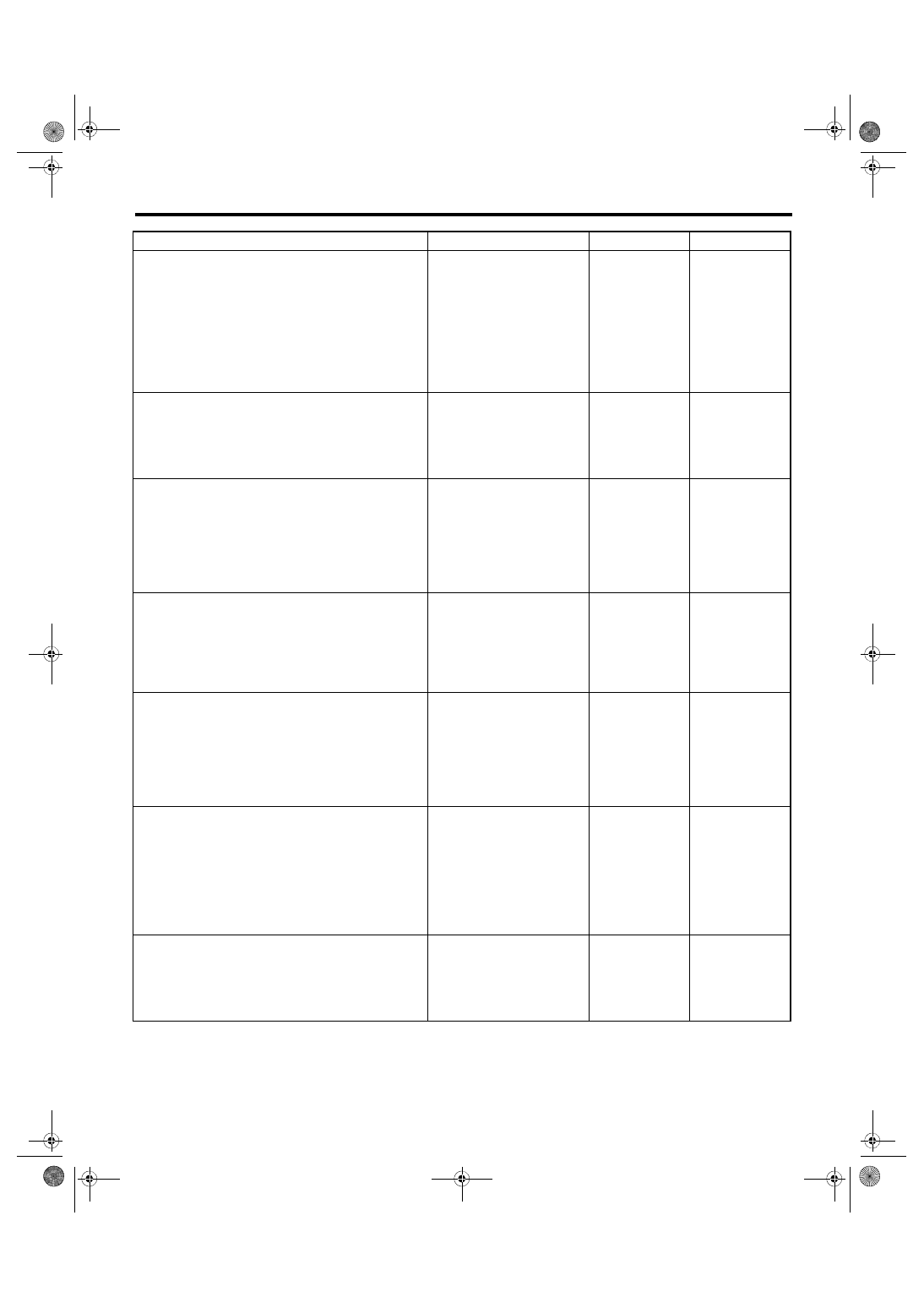
Step
Check
Yes
No
1
CHECK POWER SUPPLY FOR YAW RATE &
G SENSOR.
1) Turn the ignition switch to OFF.
2) Disconnect the connector from yaw rate & G
sensor.
3) Turn the ignition switch to ON.
4) Measure the voltage between yaw rate & G
sensor and chassis ground.
Connector & terminal
(B230) No. 1 (+) — Chassis ground (–):
Is the voltage 10 — 15 V?
Repair the yaw rate
& G sensor power
supply circuit.
2
CHECK YAW RATE & G SENSOR GROUND
CIRCUIT.
Measure the resistance between yaw rate & G
sensor and chassis ground.
Connector & terminal
(B230) No. 4 — Chassis ground:
Is the resistance less than 10
Ω?
Repair the yaw rate
& G sensor ground
circuit.
3
CHECK YAW RATE & G SENSOR HARNESS.
1) Disconnect the connector from the
VDCCM&H/U.
2) Measure the resistance between
VDCCM&H/U and yaw rate & G sensor.
Connector & terminal
(B230) No. 3 — (B310) No. 10:
(B230) No. 2 — (B310) No. 35:
Is the resistance less than 1 Ω? Go to step
Repair the harness
between yaw rate
& G sensor and
VDCCM&H/U.
4
CHECK GROUND SHORT CIRCUIT IN YAW
RATE & G SENSOR HARNESS.
Measure the resistance between yaw rate & G
sensor and chassis ground.
Connector & terminal
(B230) No. 2 — Chassis ground:
(B230) No. 3 — Chassis ground:
Is the resistance 1 MΩ or
more?
Repair the harness
between yaw rate
& G sensor and
VDCCM&H/U.
5
CHECK YAW RATE & G SENSOR.
1) Turn the ignition switch to OFF.
2) Connect all connectors.
3) Clear the memory. <Ref. to VDC(diag)-27,
Clear Memory Mode.>
4) Perform the Inspection Mode. <Ref. to
VDC(diag)-26, Inspection Mode.>
5) Read the DTC.
Is the same DTC displayed?
6
CHECK YAW RATE & G SENSOR.
1) Turn the ignition switch to OFF.
2) Replace the yaw rate & G sensor. <Ref. to
VDC-20, Yaw Rate and G Sensor.>
3) Clear the memory. <Ref. to VDC(diag)-27,
Clear Memory Mode.>
4) Perform the Inspection Mode. <Ref. to
VDC(diag)-26, Inspection Mode.>
5) Read the DTC.
Is the same DTC displayed?
7
CHECK OTHER DTC DETECTION.
Is any other DTC displayed?
Temporary poor
contact occurs.
VDC(diag)-100
Diagnostic Procedure with Diagnostic Trouble Code (DTC)
VEHICLE DYNAMICS CONTROL (VDC) (DIAGNOSTICS)
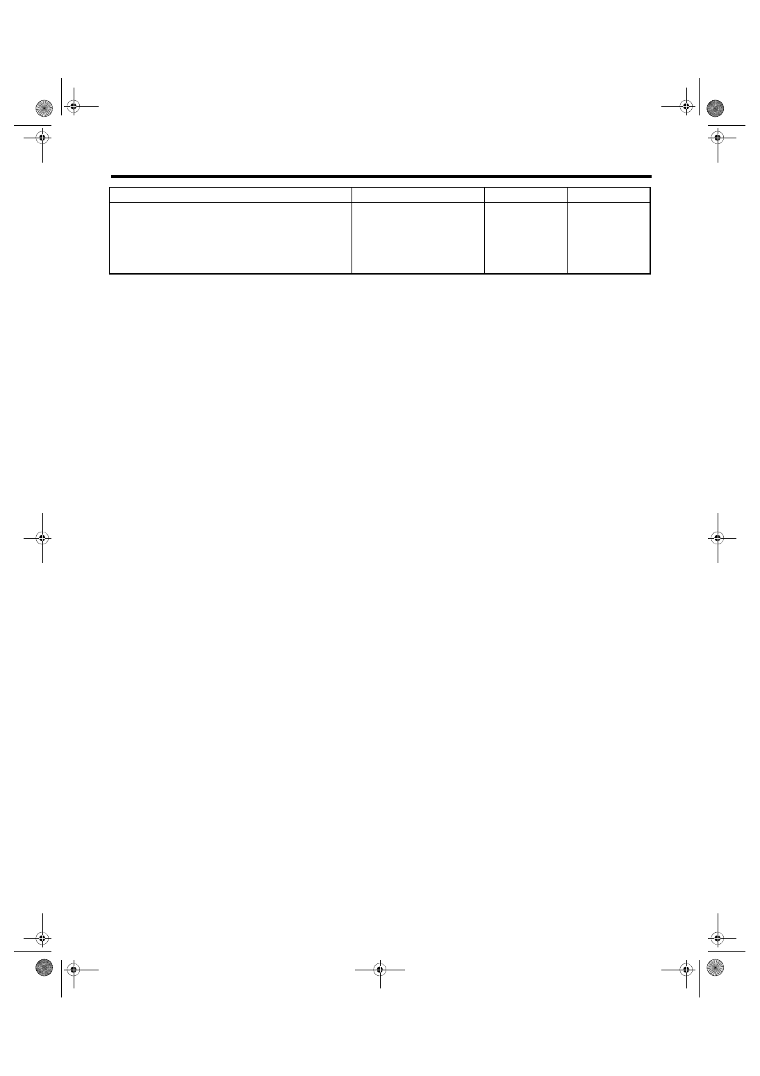
8
CHECK OTHER DTC DETECTION.
Is any other DTC displayed?
Malfunction is
found in original
yaw rate & G sen-
sor.
Step
Check
Yes
No
VDC(diag)-101
Diagnostic Procedure with Diagnostic Trouble Code (DTC)
VEHICLE DYNAMICS CONTROL (VDC) (DIAGNOSTICS)
AT:DTC C0072 SENSOR TYPE ABNORMAL
DTC DETECTING CONDITION:
Different yaw rate sensor specification
TROUBLE SYMPTOM:
• VDC does not operate.
• Hill start assist does not operate.
AU:DTC C0073 LATERAL G SENSOR OFFSET IS TOO BIG
NOTE:
For the diagnostic procedure, refer to “DTC C0073 EXCESSIVE LATERAL G SENSOR SIGNAL”. <Ref. to
VDC(diag)-102, DTC C0073 EXCESSIVE LATERAL G SENSOR SIGNAL, Diagnostic Procedure with Diag-
AV:DTC C0073 ABNORMAL LATERAL G SENSOR OUTPUT
NOTE:
For the diagnostic procedure, refer to “DTC C0073 EXCESSIVE LATERAL G SENSOR SIGNAL”. <Ref. to
VDC(diag)-102, DTC C0073 EXCESSIVE LATERAL G SENSOR SIGNAL, Diagnostic Procedure with Diag-
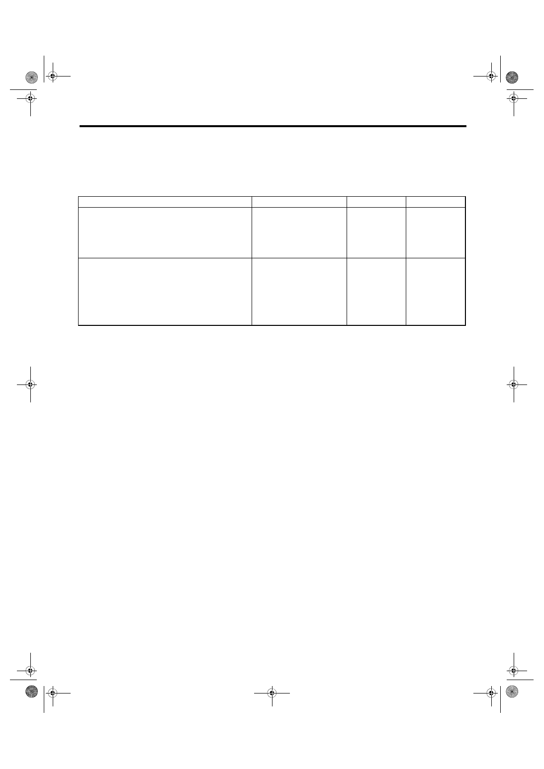
Step
Check
Yes
No
1
CHECK YAW RATE & G SENSOR IDENTIFI-
CATION MARK.
Check the identification mark on the sticker
applied on the top of the yaw rate & G sensor.
Is the identification symbol cor-
rect?
MT: R
Replace the yaw
rate & G sensor
with a genuine
part. <Ref. to VDC-
20, Yaw Rate and
G Sensor.>
2
CHECK VDCCM&H/U IDENTIFICATION
SYMBOL.
Check the identification mark stamped on the
upper side of the H/U. <Ref. to VDC-2, SPECI-
FICATION, General Description.>
Is the identification symbol cor-
rect?
Replace the
VDCCM&H/U.
<Ref. to VDC-8,
VDC Control Mod-
ule and Hydraulic
Control Unit
(VDCCM&H/U).>
VDC(diag)-102
Diagnostic Procedure with Diagnostic Trouble Code (DTC)
VEHICLE DYNAMICS CONTROL (VDC) (DIAGNOSTICS)
AW:DTC C0073 EXCESSIVE LATERAL G SENSOR SIGNAL
DTC DETECTING CONDITION:
Defective lateral G sensor
TROUBLE SYMPTOM:
VDC does not operate.
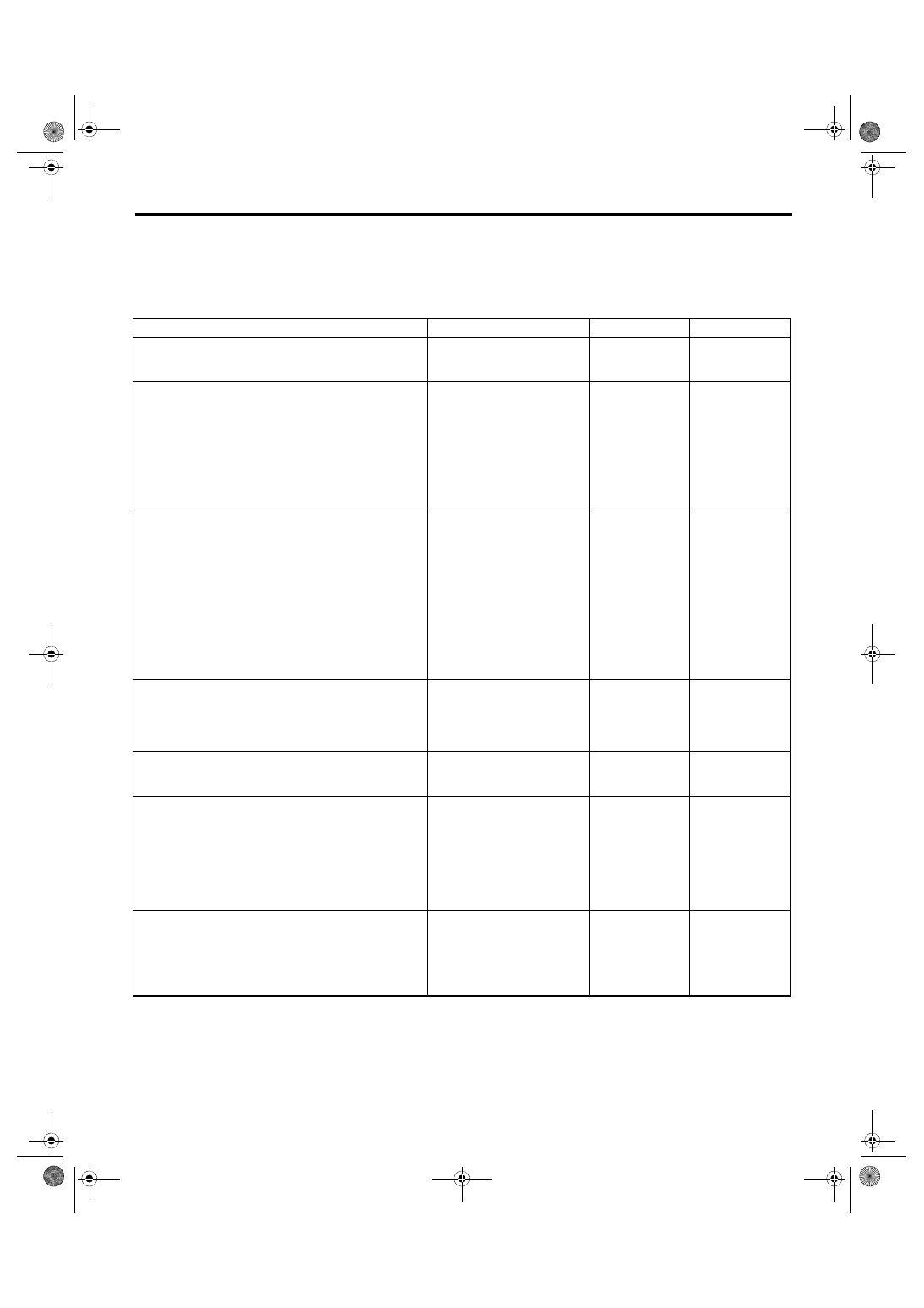
Step
Check
Yes
No
1
CHECK YAW RATE & G SENSOR INSTAL-
LATION.
Is the yaw rate & G sensor
installation bolt tightened to 7.5
N·m (0.76 kgf-m, 5.5 ft-lb)?
Tighten the yaw
rate & G sensor
installation bolt.
2
CHECK OUTPUT OF LATERAL G SENSOR
WITH SUBARU SELECT MONITOR.
1) Park the vehicle on a level surface.
2) Select “Current Data Display & Save” on the
Subaru Select Monitor. <Ref. to VDC(diag)-19,
READ CURRENT DATA, OPERATION, Subaru
Select Monitor.>
3) Read the «Lateral G Sensor output» dis-
played on display.
Is the indicated reading on the
monitor display –1.5 — 1.5 m/s
2
?
Replace the yaw
rate & G sensor.
<Ref. to VDC-20,
Yaw Rate and G
Sensor.>
3
CHECK OUTPUT OF LATERAL G SENSOR
WITH SUBARU SELECT MONITOR.
1) Turn the ignition switch to OFF.
2) Remove the yaw rate & G sensor from vehi-
cle.
3) Turn the ignition switch to ON, and select the
“Current Data Display & Save” in Subaru Select
Monitor. <Ref. to VDC(diag)-19, READ CUR-
RENT DATA, OPERATION, Subaru Select
Monitor.>
4) Read the «Lateral G Sensor output» dis-
played on display.
When the yaw rate & G sensor is
inclined 90° to the right, is the
indicated value 6.8 — 12.8 m/s
2
?
Replace the yaw
rate & G sensor.
<Ref. to VDC-20,
Yaw Rate and G
Sensor.>
4
CHECK LATERAL G SENSOR WITH SUBA-
RU SELECT MONITOR.
Read the «Lateral G Sensor output» displayed
on display.
When the yaw rate & G sensor
is inclined 90° to the left, is the
indicated value –6.8 — –12.8
m/s
2
?
Replace the yaw
rate & G sensor.
<Ref. to VDC-20,
Yaw Rate and G
Sensor.>
5
CHECK POOR CONTACT OF CONNEC-
TORS.
Turn the ignition switch to OFF.
Is there poor contact of connec-
tor between VDCCM&H/U and
yaw rate & G sensor?
Repair the connec-
tor.
6
CHECK VDCCM&H/U.
1) Connect all connectors.
2) Clear the memory. <Ref. to VDC(diag)-27,
Clear Memory Mode.>
3) Perform the Inspection Mode. <Ref. to
VDC(diag)-26, Inspection Mode.>
4) Read the DTC.
Is the same DTC displayed?
7
CHECK OTHER DTC DETECTION.
Is any other DTC displayed?
Temporary poor
contact occurs.
Нет комментариевНе стесняйтесь поделиться с нами вашим ценным мнением.
Текст