Subaru Impreza 3 / Impreza WRX / Impreza WRX STI. Service manual — part 549
VDC(diag)-95
Diagnostic Procedure with Diagnostic Trouble Code (DTC)
VEHICLE DYNAMICS CONTROL (VDC) (DIAGNOSTICS)
Step
Check
Yes
No
1
CHECK POWER SUPPLY OF YAW RATE & G
SENSOR.
1) Turn the ignition switch to OFF.
2) Disconnect the connector from yaw rate & G
sensor.
3) Turn the ignition switch to ON.
4) Measure the voltage between yaw rate & G
sensor and chassis ground.
Connector & terminal
(B230) No. 1 (+) — Chassis ground (–):
Is the voltage 10 — 15 V?
Repair the yaw rate
& G sensor power
supply circuit.
2
CHECK YAW RATE & G SENSOR GROUND
CIRCUIT.
Measure the resistance between yaw rate & G
sensor and chassis ground.
Connector & terminal
(B230) No. 4 — Chassis ground:
Is the resistance less than 10
Ω?
Repair the yaw rate
& G sensor ground
circuit.
3
CHECK YAW RATE & G SENSOR.
1) Turn the ignition switch to OFF.
2) Connect all connectors.
3) Clear the memory. <Ref. to VDC(diag)-27,
Clear Memory Mode.>
4) Perform the Inspection Mode. <Ref. to
VDC(diag)-26, Inspection Mode.>
5) Read the DTC.
Is the same DTC displayed?
Replace the yaw
rate & G sensor.
<Ref. to VDC-20,
Yaw Rate and G
Sensor.>
4
CHECK OTHER DTC DETECTION.
Is any other DTC displayed?
Temporary poor
contact occurs.
VDC(diag)-96
Diagnostic Procedure with Diagnostic Trouble Code (DTC)
VEHICLE DYNAMICS CONTROL (VDC) (DIAGNOSTICS)
AR:DTC C0072 CHANGE RANGE OF YAW RATE SENSOR SIGNAL IS TOO BIG
DTC DETECTING CONDITION:
Defective yaw rate sensor
TROUBLE SYMPTOM:
VDC does not operate.
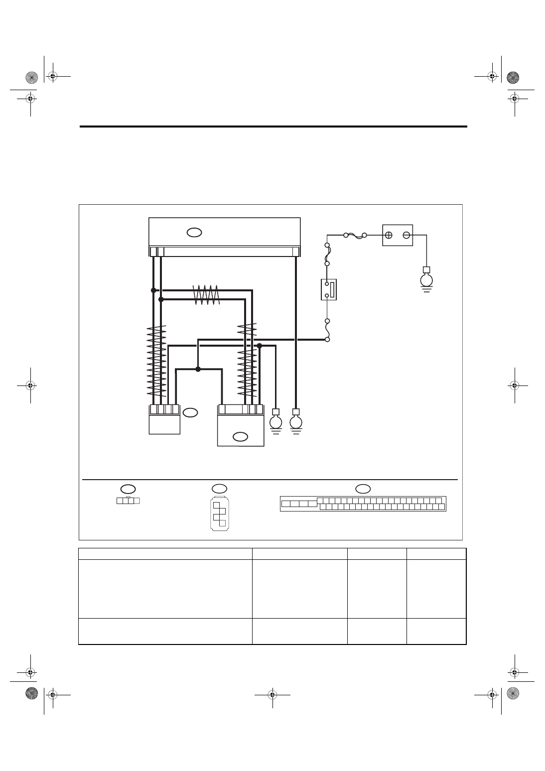
WIRING DIAGRAM:
Vehicle dynamics control system <Ref. to WI-67, Vehicle Dynamics Control System.>
Step
Check
Yes
No
1
INTERVIEW CUSTOMERS.
Check if the vehicle ran the road with banks or
sandy surface (which does not mean a dirt
road).
Did the vehicle run the road
with banks or sandy surface
(which does not mean a dirt
road)?
VDCCM&H/U may
record DTC when
the vehicle ran the
road with banks or
sandy surface
(which does not
mean a dirt road).
2
CHECK YAW RATE & G SENSOR INSTAL-
LATION.
Is the yaw rate & G sensor
installation bolt tightened to 7.5
N·m (0.76 kgf-m, 5.5 ft-lb)?
Tighten the yaw
rate & G sensor
installation bolt.
VDC00702
1 2 3 4
B310 VDCCM & H/U
25
10
35
B231
B230
2
4
1
3
1
4
2
3
STEERING
ANGLE
SENSOR
YAW RATE &
G SENSOR
E
B231
SBF-6
MAIN SBF
No.33
E
IGNITION SWITCH
BATTERY
E
B310
4 5 6 7 8 9
26 27 28 29 30
2 3
1
31 32 33 34 35 36
10 11
14 15 16 17 18 19
37 38 39 40
12 13
41 42 43 44 45 46
20 21
23 24
22
25
B230
1
2
3
4
TWISTED P
AIR LINE
TWISTED P
AIR LINE
TWISTED PAIR LINE
VDC(diag)-97
Diagnostic Procedure with Diagnostic Trouble Code (DTC)
VEHICLE DYNAMICS CONTROL (VDC) (DIAGNOSTICS)
3
CHECK POWER SUPPLY OF YAW RATE & G
SENSOR.
1) Turn the ignition switch to OFF.
2) Disconnect the connector from yaw rate & G
sensor.
3) Turn the ignition switch to ON.
4) Measure the voltage between yaw rate & G
sensor and chassis ground.
Connector & terminal
(B230) No. 1 (+) — Chassis ground (–):
Is the voltage 10 — 15 V?
Repair the yaw rate
& G sensor power
supply circuit.
4
CHECK YAW RATE & G SENSOR GROUND
CIRCUIT.
Measure the resistance between yaw rate & G
sensor and chassis ground.
Connector & terminal
(B230) No. 4 — Chassis ground:
Is the resistance less than 10
Ω?
Repair the yaw rate
& G sensor ground
circuit.
5
CHECK OUTPUT OF YAW RATE & G SEN-
SOR WITH SUBARU SELECT MONITOR.
1) Drive the vehicle on a flat road.
2) Park the vehicle straight.
3) Select “Current Data Display & Save” on the
Subaru Select Monitor. <Ref. to VDC(diag)-19,
READ CURRENT DATA, OPERATION, Subaru
Select Monitor.>
4) Read the «Yaw Rate Sensor Output» dis-
played on display.
Is the reading indicated on
monitor display –4 — 4 deg/s?
Replace the yaw
rate & G sensor.
<Ref. to VDC-20,
Yaw Rate and G
Sensor.>
6
CHECK YAW RATE & G SENSOR.
1) Turn the ignition switch to OFF.
2) Connect all connectors.
3) Clear the memory. <Ref. to VDC(diag)-27,
Clear Memory Mode.>
4) Perform the Inspection Mode. <Ref. to
VDC(diag)-26, Inspection Mode.>
5) Read the DTC.
Is the same DTC displayed?
7
CHECK VDCCM&H/U.
1) Turn the ignition switch to OFF.
2) Replace the yaw rate & G sensor. <Ref. to
VDC-20, Yaw Rate and G Sensor.>
3) Clear the memory. <Ref. to VDC(diag)-27,
Clear Memory Mode.>
4) Perform the Inspection Mode. <Ref. to
VDC(diag)-26, Inspection Mode.>
5) Read the DTC.
Is the same DTC displayed?
8
CHECK OTHER DTC DETECTION.
Is any other DTC displayed?
Temporary poor
contact occurs.
9
CHECK OTHER DTC DETECTION.
Is any other DTC displayed?
Malfunction is
found in original
yaw rate & G sen-
sor.
Step
Check
Yes
No
VDC(diag)-98
Diagnostic Procedure with Diagnostic Trouble Code (DTC)
VEHICLE DYNAMICS CONTROL (VDC) (DIAGNOSTICS)
AS:DTC C0072 YAW RATE SENSOR COMMUNICATION
DTC DETECTING CONDITION:
Communication failure between yaw rate sensor and VDCCM
TROUBLE SYMPTOM:
• ABS does not operate.
• VDC does not operate.
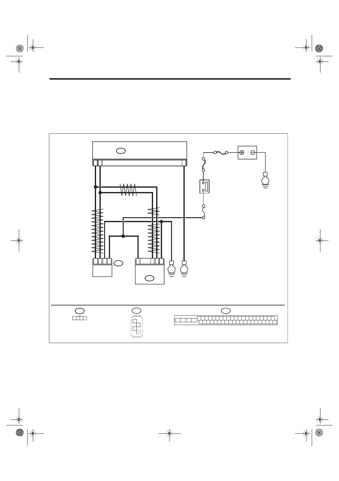
WIRING DIAGRAM:
Vehicle Dynamics Control System <Ref. to WI-67, Vehicle Dynamics Control System.>
VDC00702
1 2 3 4
B310 VDCCM & H/U
25
10
35
B231
B230
2
4
1
3
1
4
2
3
STEERING
ANGLE
SENSOR
YAW RATE &
G SENSOR
E
B231
SBF-6
MAIN SBF
No.33
E
IGNITION SWITCH
BATTERY
E
B310
4 5 6 7 8 9
26 27 28 29 30
2 3
1
31 32 33 34 35 36
10 11
14 15 16 17 18 19
37 38 39 40
12 13
41 42 43 44 45 46
20 21
23 24
22
25
B230
1
2
3
4
TWISTED P
AIR LINE
TWISTED P
AIR LINE
TWISTED PAIR LINE
Нет комментариевНе стесняйтесь поделиться с нами вашим ценным мнением.
Текст