Subaru Impreza 3 / Impreza WRX / Impreza WRX STI. Service manual — part 552
VDC(diag)-107
Diagnostic Procedure with Diagnostic Trouble Code (DTC)
VEHICLE DYNAMICS CONTROL (VDC) (DIAGNOSTICS)
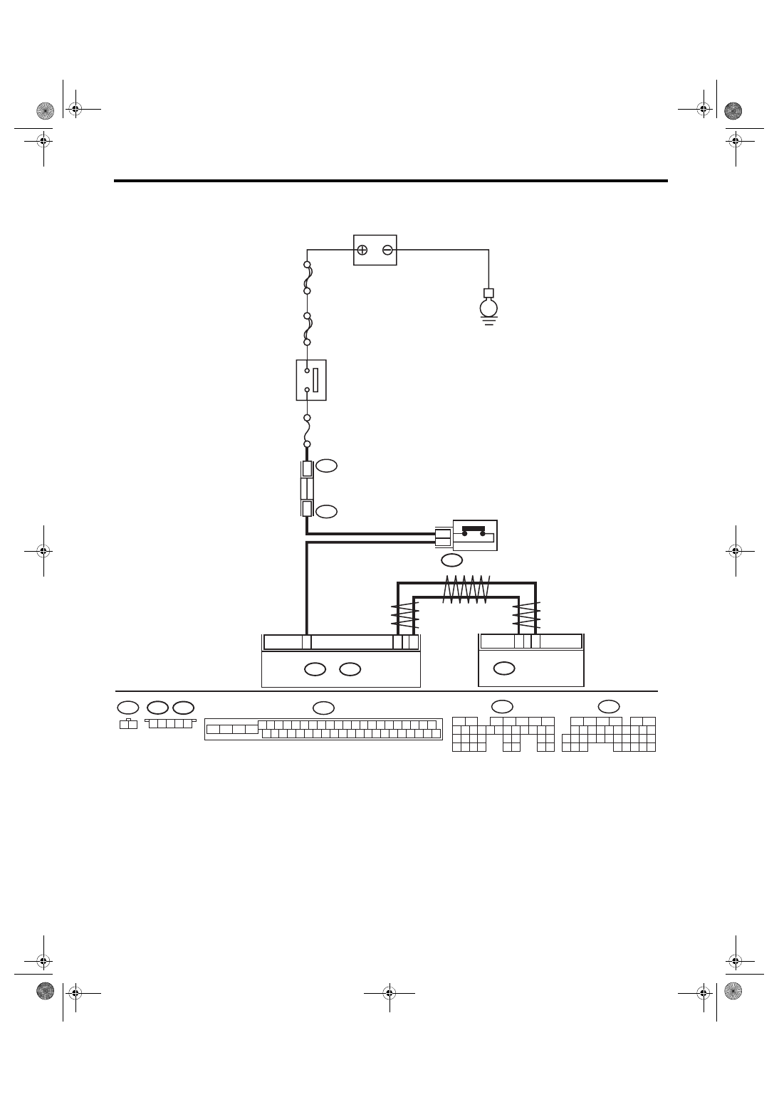
WIRING DIAGRAM:
Engine electrical system <Ref. to WI-32, Engine Electrical System.>
VDC00891
B136
C:
B135
B:
B9
C17
C2
8
B107
B440
B441
1
2
B310
35
10
B441
B440
1
1
B: B135
29
4
3
1
2
7
6
5
10 11 12 13 14 15
25
24
16
30
9
8
17 18 19
20
28
21 22 23
32
31
26 27
33
34 35
35
27
16
10 11 12 13 14 15
25
24
30
9
8
7
17 18 19 20
28
21 22 23
29
32
31
1
2
3
4
5
6
26
33 34
B136
C:
2
1
B107
25
22
24
23
21
20
46
45
44
43
42
41
13
12
40
39
38
37
19
18
17
16
15
14
11
10
36
35
34
33
32
31
1
3
2
30
29
28
27
26
9
8
7
6
5
4
B310
5
4
3
2
1
ECM
E
SBF-
8
VDCCM & H/U
IG 2 RELAY
CLUTCH SWITCH
BATTERY
No.
4
MAIN SBF
VDC(diag)-108
Diagnostic Procedure with Diagnostic Trouble Code (DTC)
VEHICLE DYNAMICS CONTROL (VDC) (DIAGNOSTICS)
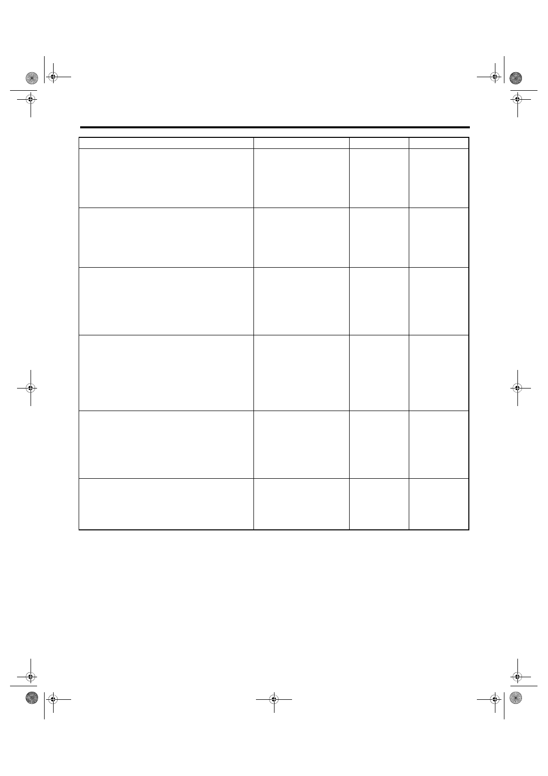
Step
Check
Yes
No
1
CHECK LAN SYSTEM.
Perform the diagnosis for LAN system. <Ref. to
LAN(diag)-2, Basic Diagnostic Procedure.>
Is there any fault in LAN sys-
tem?
2
CHECK CLUTCH SIGNAL USING SUBARU
SELECT MONITOR.
1) Select “Current Data Display & Save” on the
Subaru Select Monitor. <Ref. to VDC(diag)-19,
READ CURRENT DATA, OPERATION, Subaru
Select Monitor.>
2) Read the «Clutch Signal».
Is “OFF” displayed when the
clutch pedal is not depressed,
and is “ON” displayed when
depressed?
3
CHECK CLUTCH SIGNAL OF ECM USING
SUBARU SELECT MONITOR.
1) Select “Current Data Display & Save” on
Subaru Select Monitor. <Ref. to
EN(H4DOTC)(diag)-41, READ CURRENT
DATA FOR ENGINE (NORMAL MODE),
OPERATION, Subaru Select Monitor.>
2) Read the «Clutch Signal».
Is “OFF” displayed when the
clutch pedal is not depressed,
and is “ON” displayed when
depressed?
4
CHECK HARNESS BETWEEN ECM AND
CLUTCH SWITCH.
1) Turn the ignition switch to OFF.
2) Disconnect the connectors from ECM and
clutch switch.
3) Measure the resistance of harness between
ECM and clutch switch connector.
Connector & terminal
(B135) No. 9 — (B107) No. 2:
Is the resistance less than 1 Ω? Repair the power
supply circuit of
clutch switch. Or
replace the clutch
switch. <Ref. to
CL-33, Clutch
Switch.>
Repair the harness
between ECM and
clutch switch con-
nector.
5
CHECK VDCCM&H/U.
1) Connect all connectors.
2) Clear the memory. <Ref. to VDC(diag)-27,
Clear Memory Mode.>
3) Perform the Inspection Mode. <Ref. to
VDC(diag)-26, Inspection Mode.>
4) Read the DTC.
Is the same DTC displayed?
6
CHECK OTHER DTC DETECTION.
Is any other DTC displayed?
Temporary poor
contact occurs.
VDC(diag)-109
Diagnostic Procedure with Diagnostic Trouble Code (DTC)
VEHICLE DYNAMICS CONTROL (VDC) (DIAGNOSTICS)
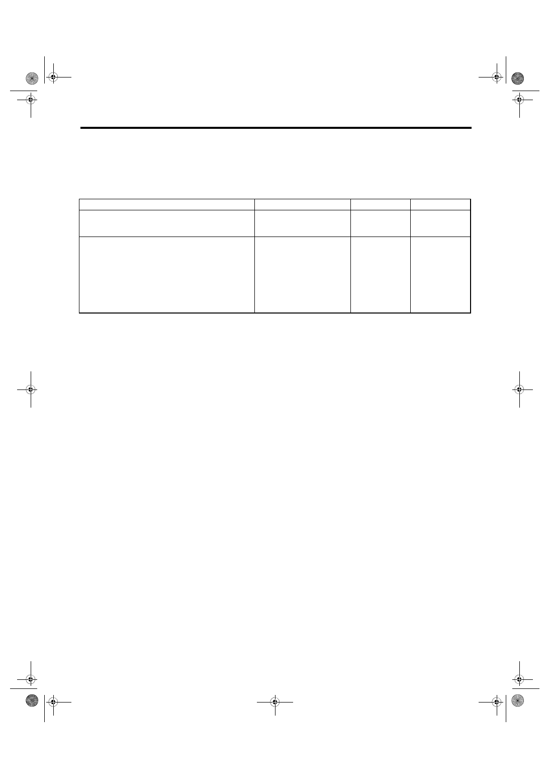
BA:DTC C0081 SYSTEM FAILURE
DTC DETECTING CONDITION:
VDC long time sequential control
TROUBLE SYMPTOM:
• ABS does not operate.
• VDC does not operate.
Step
Check
Yes
No
1
CHECK POOR CONTACT OF CONNECTOR. Is there poor contact of the
VDCCM&H/U and yaw rate & G
sensor connector?
Repair the connec-
tor.
2
CHECK VDCCM&H/U.
1) Replace the yaw rate & G sensor. <Ref. to
VDC-20, Yaw Rate and G Sensor.>
2) Connect all connectors.
3) Clear the memory. <Ref. to VDC(diag)-27,
Clear Memory Mode.>
4) Perform the Inspection Mode. <Ref. to
VDC(diag)-26, Inspection Mode.>
5) Read the DTC.
Is the same DTC displayed?
Replace the
VDCCM&H/U.
<Ref. to VDC-8,
VDC Control Mod-
ule and Hydraulic
Control Unit
(VDCCM&H/U).>
Malfunction is
found in original
yaw rate & G sen-
sor.
VDC(diag)-110
General Diagnostic Table
VEHICLE DYNAMICS CONTROL (VDC) (DIAGNOSTICS)
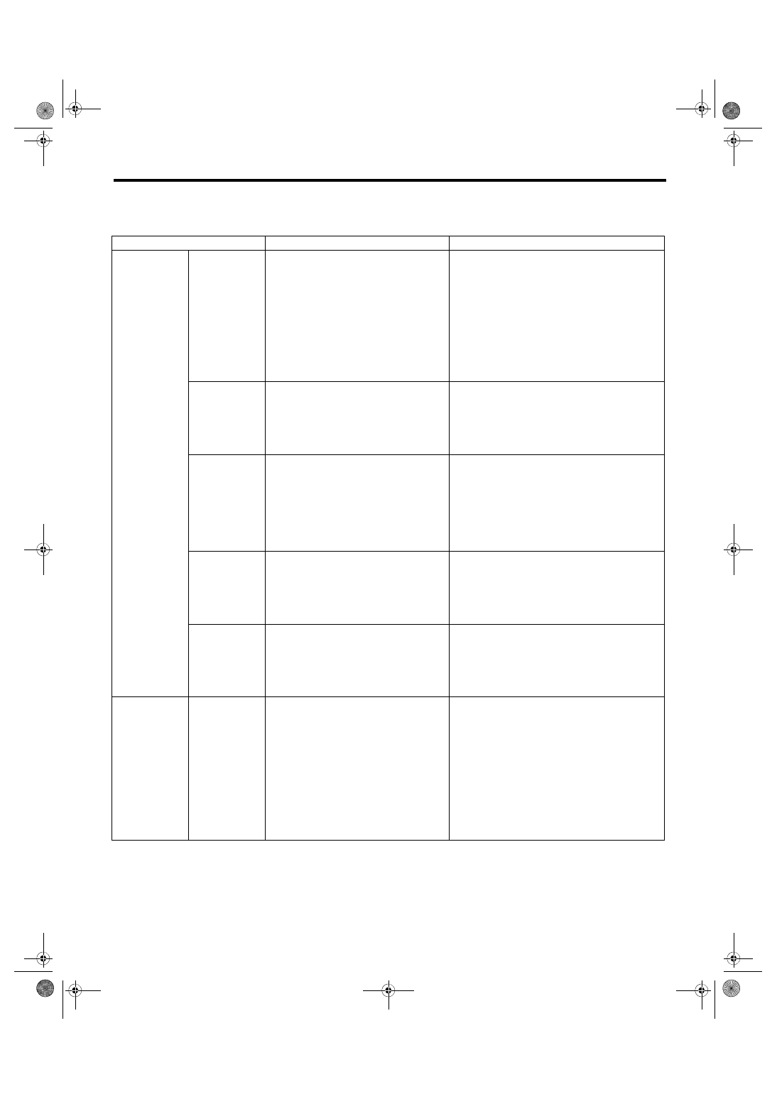
13.General Diagnostic Table
A: INSPECTION
Symptoms
Main probable cause
Other probable cause
Poor brake per-
formance
Long braking/
stopping dis-
tance
• VDCCM&H/U
• Brake pad
• Aeration to brake line
• Tire specifications, tire wear and air
pressures
• Incorrect wiring or piping connections
• Defective ABS wheel speed sensor or sensor
gap
• Defective steering angle sensor or improper
neutral position
• Defective yaw rate & G sensor or improper
installation
• Master cylinder
• Brake caliper
• Disc rotor
• Brake pipe
• Brake booster
Wheel lock
• VDCCM&H/U
• Defective ABS wheel speed sensor or
sensor gap
• Incorrect wiring or piping connections
• Defective steering angle sensor or improper
neutral position
• Defective yaw rate & G sensor or improper
installation
• Brake caliper
• Brake pipe
Brake drag
• VDCCM&H/U
• Defective ABS wheel speed sensor or
sensor gap
• Master cylinder
• Brake caliper
• Parking brake
• Axle and wheels
• Brake pedal play
• Defective steering angle sensor or improper
neutral position
• Defective yaw rate & G sensor or improper
installation
• Brake pad
• Brake pipe
Long brake
pedal stroke
• Aeration to brake line
• Brake pedal play
• VDCCM&H/U
• Master cylinder
• Brake caliper
• Brake pad
• Brake pipe
• Brake booster
Vehicle vertical
pitching
• VDCCM&H/U
• Road surface (uneven)
• Suspension play or fatigue (reduced
damping)
• Incorrect wiring or piping connections
• Defective ABS wheel speed sensor or sensor
gap
• Defective steering angle sensor or improper
neutral position
• Defective yaw rate & G sensor or improper
installation
Poor brake per-
formance
Unstable or
uneven braking
• VDCCM&H/U
• Defective ABS wheel speed sensor or
sensor gap
• Brake caliper
• Brake pad
• Road surface (uneven)
• Tire specifications, tire wear and air
pressures
• Incorrect wiring or piping connections
• Defective ABS wheel speed sensor or sensor
gap
• Defective steering angle sensor or improper
neutral position
• Defective yaw rate & G sensor or improper
installation
• Master cylinder
• Disc rotor
• Brake pipe
• Axle and wheels
• Road with crowns or banks
• Suspension play or fatigue (reduced damping)
Нет комментариевНе стесняйтесь поделиться с нами вашим ценным мнением.
Текст