Subaru Impreza 3 / Impreza WRX / Impreza WRX STI. Service manual — part 125
FU(w/o STI)-27
Intake Manifold
FUEL INJECTION (FUEL SYSTEMS)
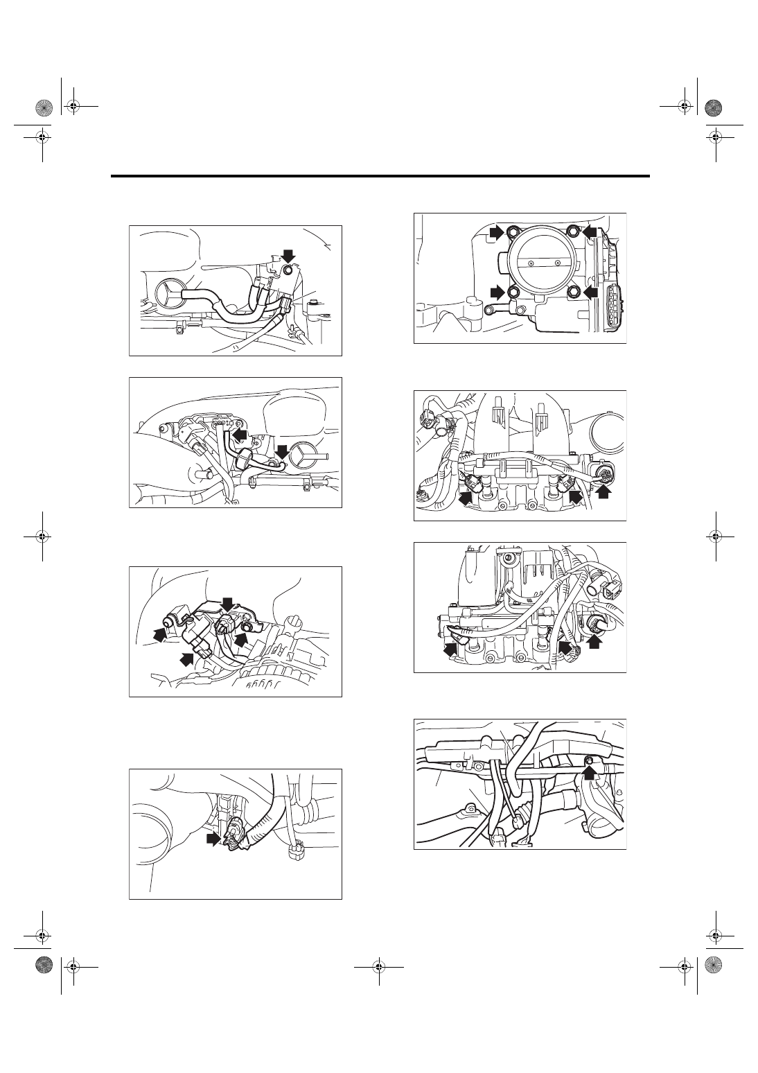
4) Disconnect the vacuum hose (B) and the con-
nector (C) from the fuel pipe, and remove the purge
control solenoid valve 1 from the intake manifold.
5) Disconnect the filter assembly.
6) Disconnect the connector from the wastegate
control solenoid valve and the manifold absolute
pressure sensor, and remove the solenoid valve
bracket assembly from the intake manifold.
7) Disconnect the connector from the purge control
solenoid valve 2, and disconnect the vacuum hose
from the intake duct and the fuel pipe.
8) Disconnect the connectors from the throttle posi-
tion sensor.
9) Remove the throttle body from the intake mani-
fold.
10) Disconnect the connector from the fuel injector
and tumble generator valve assembly.
• RH side
• LH side
11) Remove the PCV pipe (A), harness assembly
(B), intake duct (C), brake booster vacuum hose
(D) and vacuum hose (E) from the intake manifold.
FU-05440
(A)
(B)
(C)
FU-05342
FU-05365
FU-05673
FU-05674
FU-06541
FU-06542
FU-06543
(C)
(A)
(D)
(E)
(B)
FU(w/o STI)-28
Intake Manifold
FUEL INJECTION (FUEL SYSTEMS)
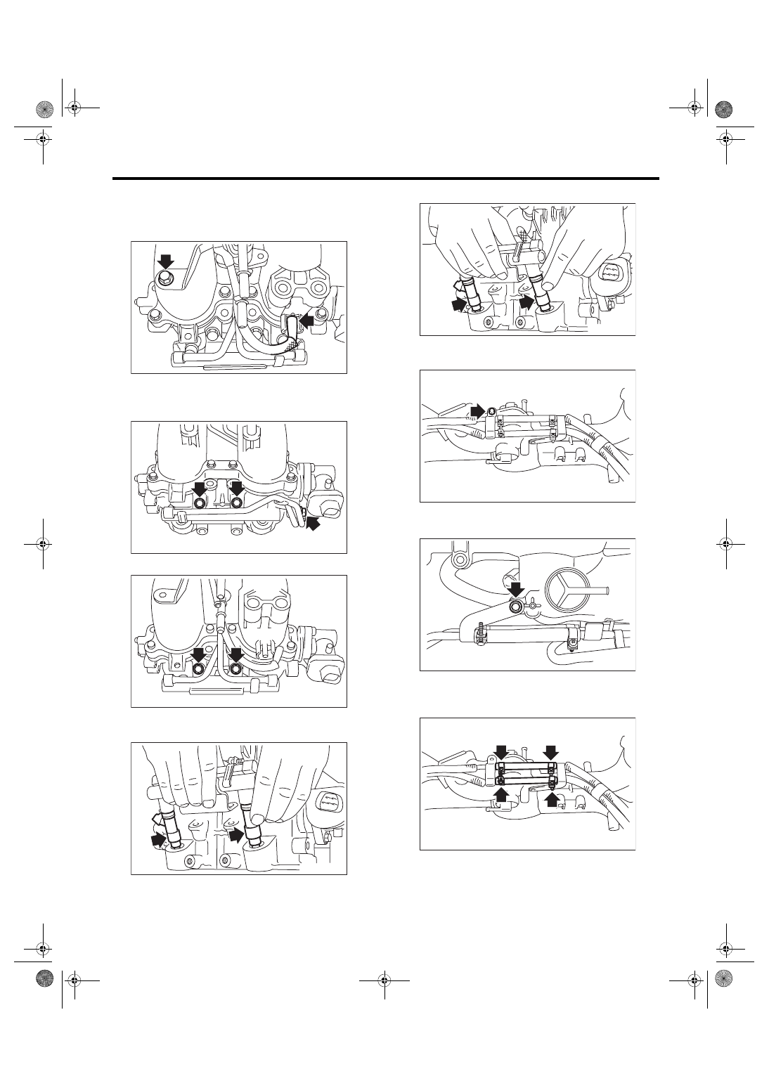
12) Remove the bolt which secures the fuel injector
pipe LH onto the intake manifold, and disconnect
the pressure regulator vacuum hose from the in-
take manifold.
13) Remove the bolts which hold fuel injector pipe
onto intake manifold.
• RH side
• LH side
14) Remove the fuel injector.
• RH side
• LH side
15) Remove the bolts which hold fuel pipe onto in-
take manifold.
16) Remove the bolt which holds fuel injector pipe
RH onto intake manifold.
17) Loosen the clamp which holds the fuel hose to
the fuel injector pipe RH and the fuel pipe, and then
disconnect the pipe from the fuel hose.
18) Remove the fuel injector pipe and the fuel pipe.
FU-06544
FU-06545
FU-06560
FU-06546
FU-06547
FU-05236
FU-05715
FU-05237
FU(w/o STI)-29
Intake Manifold
FUEL INJECTION (FUEL SYSTEMS)
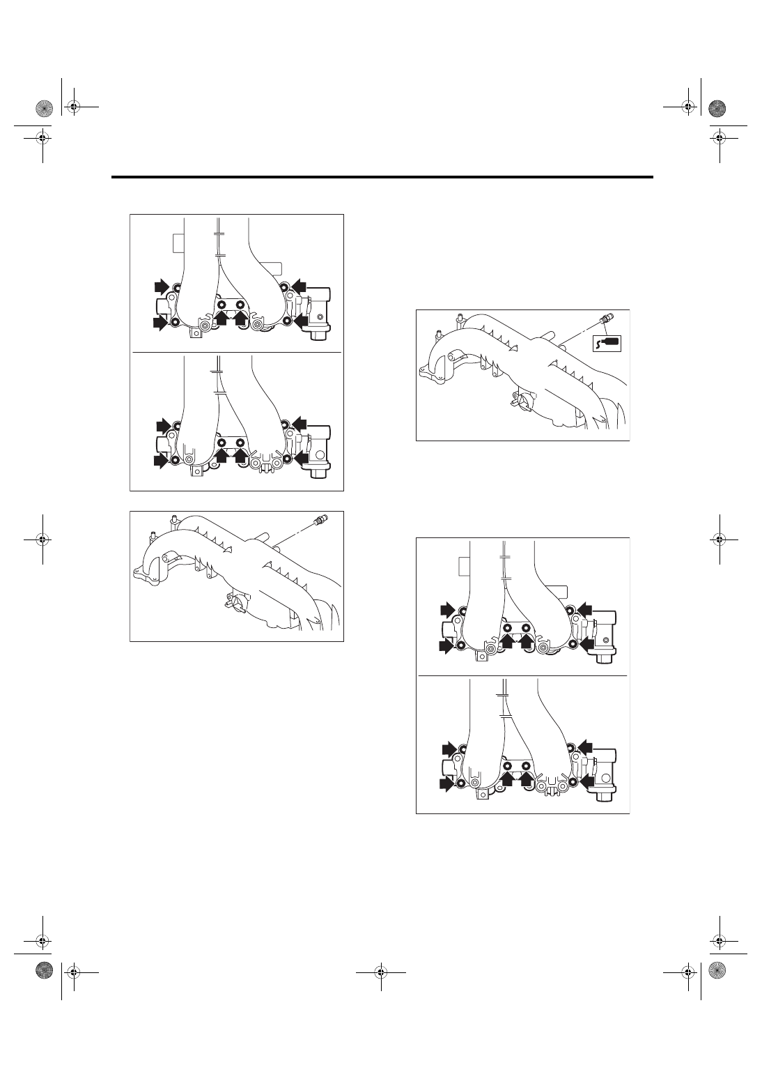
19) Remove the tumble generator valve assembly
from the intake manifold.
20) Remove the nipple from the intake manifold.
D: ASSEMBLY
1) Apply liquid gasket to the nipple threads, and in-
stall the nipple to the intake manifold.
Liquid gasket:
THREE BOND 1105 (Part No. 004403010) or
equivalent
Tightening torque:
23 N·m (2.3 kgf-m, 17.0 ft-lb)
2) Install the tumble generator valve assembly onto
intake manifold.
NOTE:
Use new O-rings.
Tightening torque:
8.3 N·m (0.8 kgf-m, 6.1 ft-lb)
3) Install the fuel injector pipe.
FU-04751
FU-05688
FU-05689
FU-04751
FU(w/o STI)-30
Intake Manifold
FUEL INJECTION (FUEL SYSTEMS)
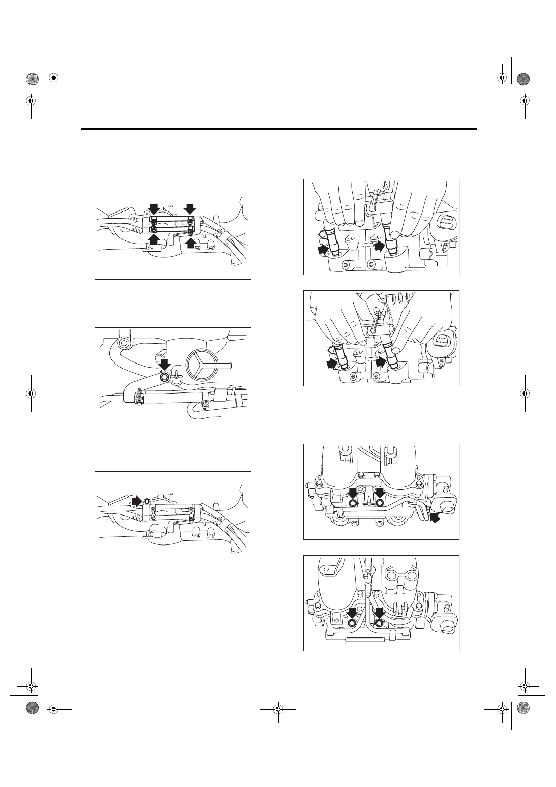
4) Connect fuel hoses to the fuel injector pipe and
the fuel pipe. <Ref. to FU(w/o STI)-93, CONNECT-
ING FUEL DELIVERY HOSE, FUEL RETURN
HOSE AND FUEL HOSE, INSTALLATION, Fuel
Delivery, Return and Evaporation Lines.>
5) Secure the fuel injector pipe RH to intake mani-
fold with bolt.
Tightening torque:
6.4 N·m (0.7 kgf-m, 4.7 ft-lb)
6) Secure the fuel pipe to intake manifold with
bolts.
Tightening torque:
6.4 N·m (0.7 kgf-m, 4.7 ft-lb)
7) Install the fuel injector.
NOTE:
Use new O-rings, rubbers and seal rings.
• RH side
• LH side
8) Secure the fuel injector pipe to intake manifold
with bolts.
Tightening torque:
19 N·m (1.9 kgf-m, 14.0 ft-lb)
• RH side
• LH side
FU-05237
FU-05715
FU-05236
FU-06546
FU-06547
FU-06545
FU-06560
Нет комментариевНе стесняйтесь поделиться с нами вашим ценным мнением.
Текст