Subaru Impreza 3 / Impreza WRX / Impreza WRX STI. Service manual — part 469
FS-11
Wheel Alignment
FRONT SUSPENSION
4) Tighten two new flange nuts.
Tightening torque:
155 N·m (15.8 kgf-m, 114.3 ft-lb)
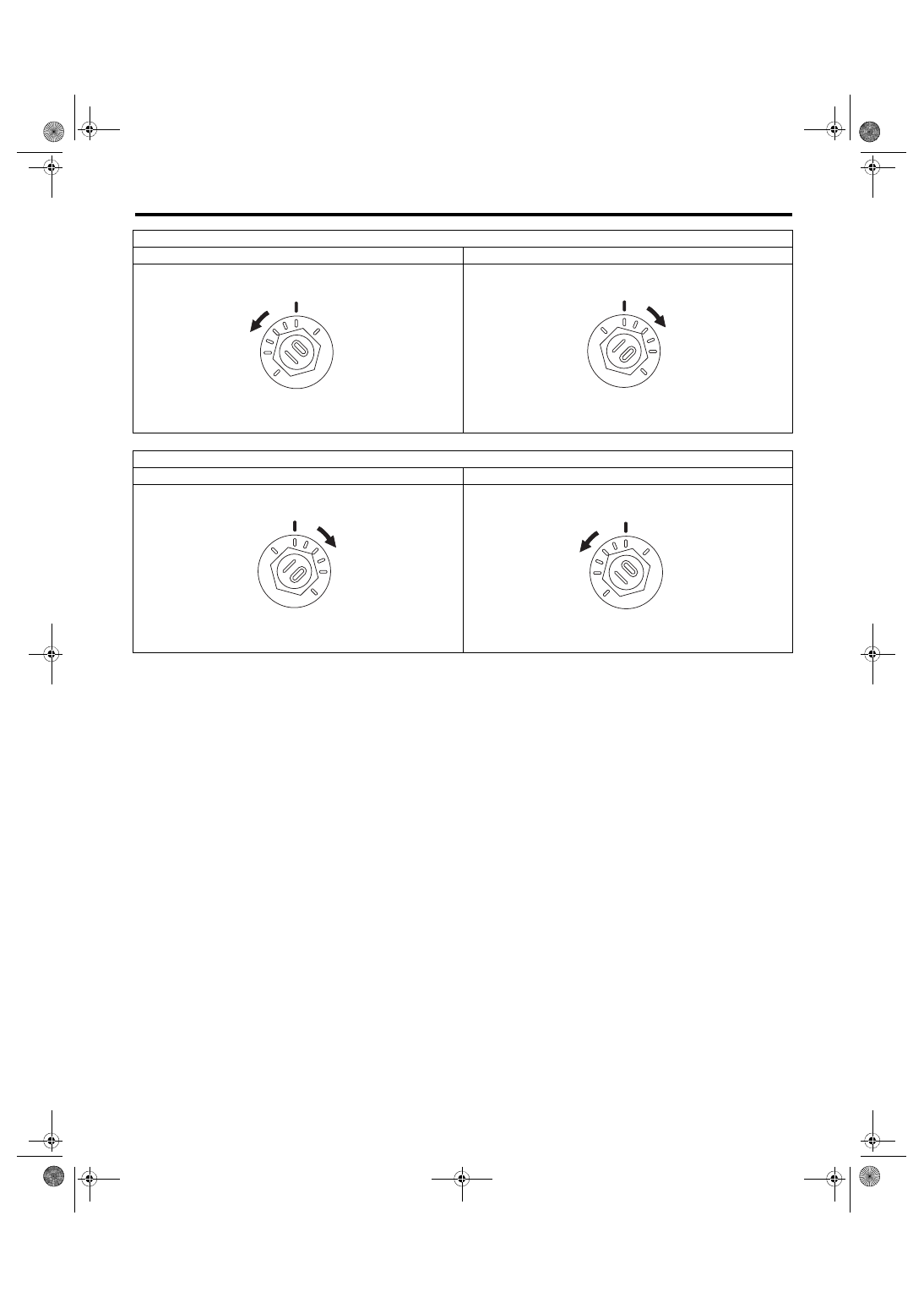
To increase camber.
Rotate the left side counterclockwise.
Rotate the right side clockwise.
To decrease camber.
Rotate the left side clockwise.
Rotate the right side counterclockwise.
FS-00009
FS-00010
FS-00010
FS-00009
FS-12
Wheel Alignment
FRONT SUSPENSION
3. CASTER
• Inspection
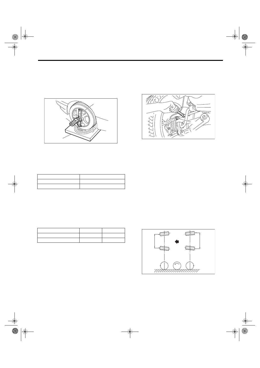
1) Place the front wheel on the turning radius
gauge. Make sure the ground contact surfaces of
the front and rear wheels are at the same height.
2) Set the adapter into the center of wheel, and
then set the wheel alignment gauge.
3) Measure the caster angle in accordance with the
operation manual for wheel alignment gauge.
4. STEERING ANGLE
• Inspection
1) Place the vehicle on turning radius gauge.
2) While depressing the brake pedal, turn the steer-
ing wheel fully to the left and right. With the steering
wheel held at each fully turned position, measure
both the inner and outer wheel steering angles.
• Adjustment
1) Turn the tie-rod to adjust the steering angle of
both inner and outer wheels.
2) Check the toe-in.
NOTE:
Correct the boot if it is twisted.
5. FRONT WHEEL TOE-IN
• Inspection
Toe-in:
0
±
3 mm (0
±
0.12 in)
1) Set the toe-in gauge in the position at wheel axis
center height behind the right and left front tires.
2) Place a mark at the center of both left and right
tires, and measure distance “A” between the
marks.
3) Move the vehicle forward to rotate the tires 180°.
NOTE:
Be sure to rotate the tires in the forward direction.
4) Measure the distance “B” between the left and
right marks. Find toe-in using the following calcula-
tion:
A – B = Toe-in
(1) Alignment gauge
(2) Turning radius gauge
(3) Adapter
Model
Caster
Except for STI model
6°30′
STI model
6°30′
Model
Inner wheel
Outer wheel
Except for STI model
36.6°±1.5°
32.2°±1.5°
STI model
36.6°±1.5°
32.2°±1.5°
FS-00213
(1)
(2)
(3)
(1) Lock nut
FS-00014
(1)
FS-00015
A
B
FS-13
Wheel Alignment
FRONT SUSPENSION
• Adjustment
When adjusting the toe-in, adjust it to the following
value.
Toe-in:
0
±
2 mm (0
±
0.08 in)
1) Check that the left and right wheel steering an-
gles are within specification.
2) Loosen the left and right side steering tie-rod
lock nuts.
3) Turn the left and right tie-rods by equal amounts
until the toe-in is at the specification.
Both the left and right tie-rods are right-hand
threaded. To increase toe-in, turn both tie-rods
clockwise by equal amount (viewing from the inside
of vehicle).
4) Tighten the tie-rod lock nut.
Tightening torque:
85 N·m (8.7 kgf-m, 62.7 ft-lb)
NOTE:
Check and correct the tie-rod boot if twisted.
6. REAR WHEEL TOE-IN
• Inspection
Toe-in:
0
±
3 mm (0
±
0.12 in)
Refer to FRONT WHEEL TOE-IN for rear toe-in in-
spection procedures. <Ref. to FS-12, FRONT
WHEEL TOE-IN, INSPECTION, Wheel Align-
ment.>
• Adjustment
When adjusting, adjust it to the following value.
Toe-in:
0
±
2 mm (0
±
0.08 in)
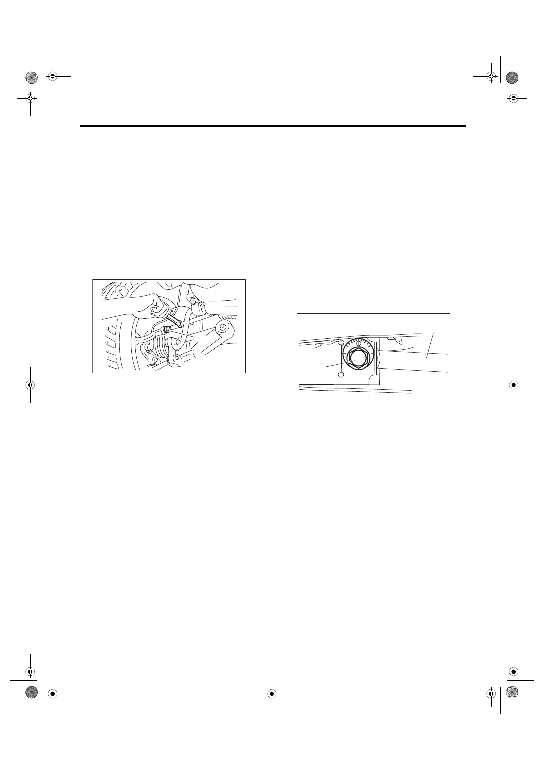
1) Loosen the self-locking nut on the inner side of
front lateral ink.
NOTE:
When loosening or tightening the adjusting bolt,
hold the bolt head and turn the self-locking nut.
2) Turn the adjusting bolt until toe-in is within the
specification.
NOTE:
When the left and right wheels are adjusted for toe-
in at the same time, the movement of one scale
graduation changes toe-in by approx. 1.3 mm (0.05
in).
(1) Lock nut
FS-00014
(1)
(1) Adjusting bolt
(2) Lateral link
FS-00372
(2)
(1)
FS-14
Wheel Alignment
FRONT SUSPENSION
3) Attach and tighten a new self-locking nut.
Tightening torque:
100 N·m (10.2 kgf-m, 73.8 ft-lb)
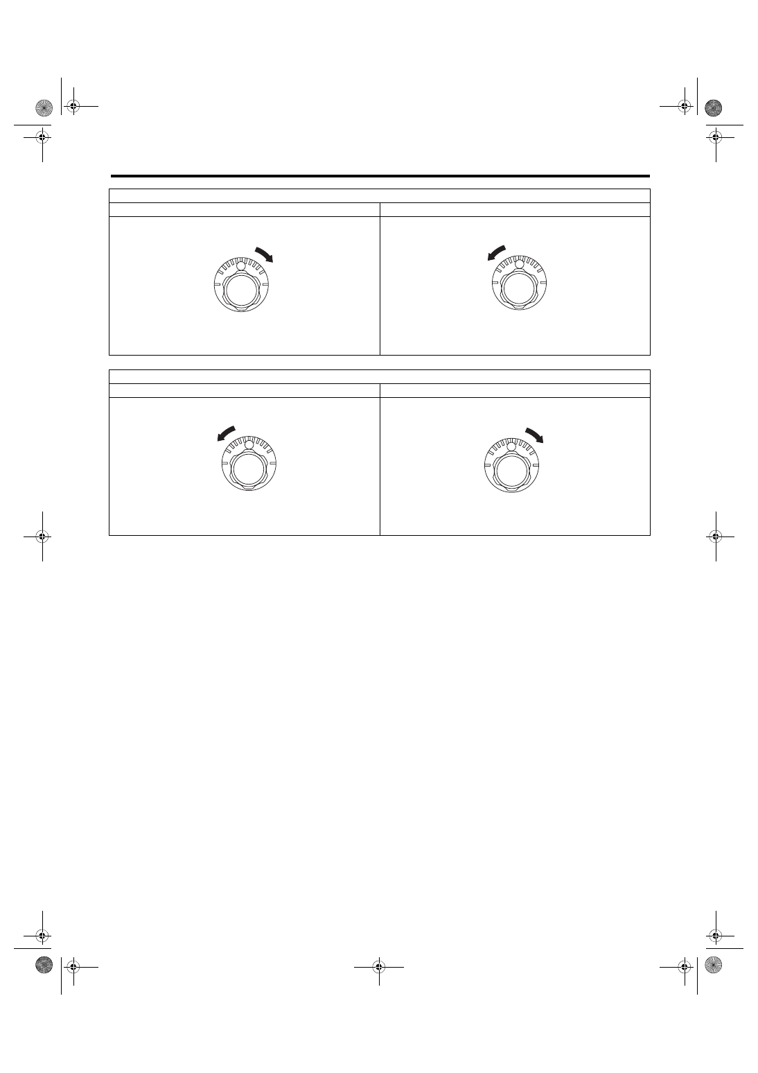
To increase toe-in.
Rotate the left side clockwise.
Rotate the right side counterclockwise.
To decrease toe-in.
Rotate the left side counterclockwise.
Rotate the right side clockwise.
FS-00018
FS-00019
FS-00019
FS-00018
Нет комментариевНе стесняйтесь поделиться с нами вашим ценным мнением.
Текст