Subaru Impreza 3 / Impreza WRX / Impreza WRX STI. Service manual — part 468
FS-7
General Description
FRONT SUSPENSION
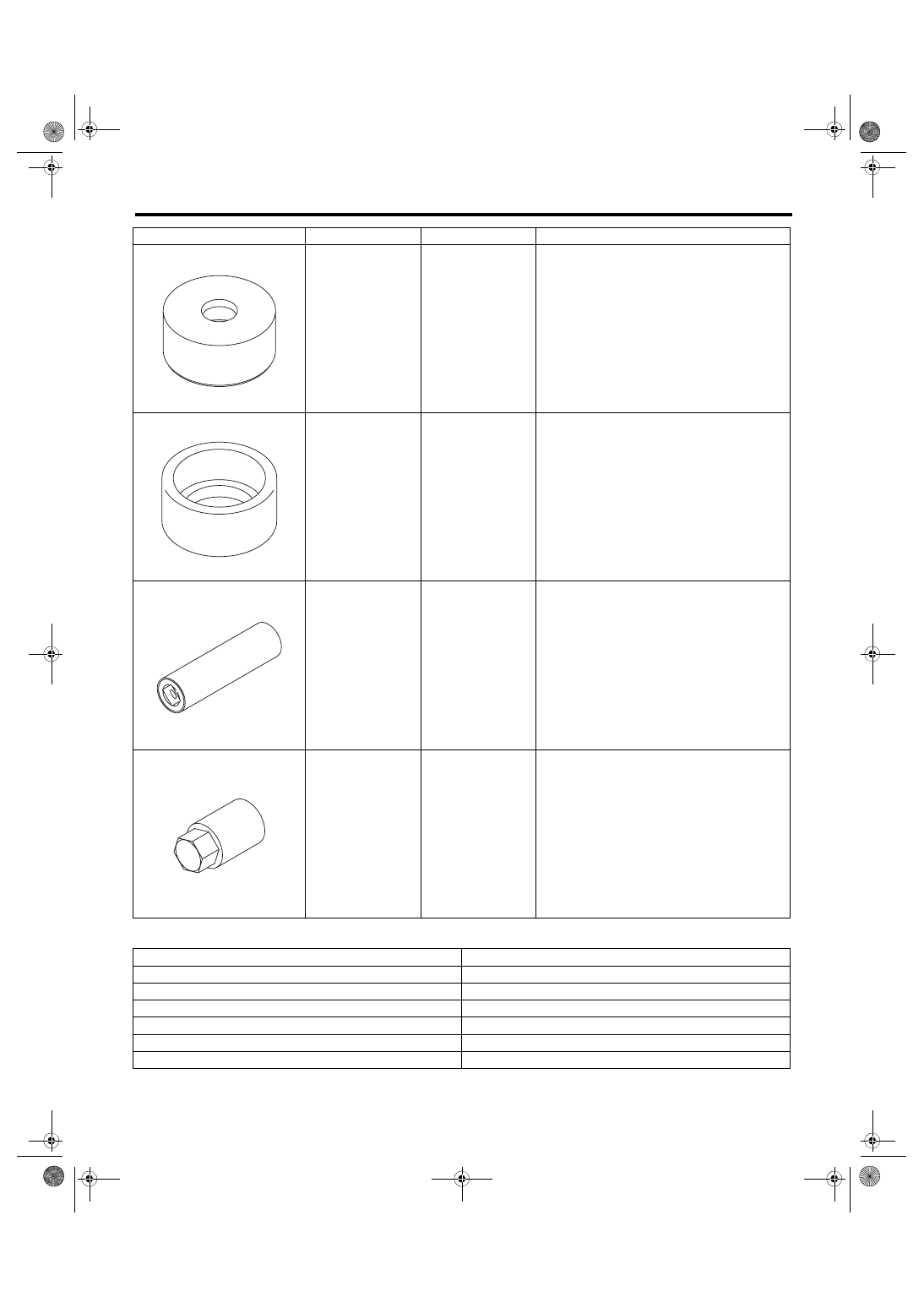
2. GENERAL TOOL
20299AG000
REMOVER
• Used for replacing front arm rear bushing.
• Used together with BASE (20299AG010).
20299AG010
BASE
• Used for replacing front arm rear bushing.
• Used together with REMOVER
(20299AG000).
20299AG020
STUD BOLT
SOCKET
Used for removing and installing the stud bolt for
front arm installing portion.
20399AG000
STRUT MOUNT
SOCKET
Used for disassembling and assembling strut
mount.
TOOL NAME
REMARKS
Alignment gauge
Used for measuring wheel alignment.
Alignment gauge adapter
Used for measuring wheel alignment.
Turning radius gauge
Used for measuring wheel alignment.
Toe-in gauge
Used for toe-in measurement.
Dial gauge
Used for damper strut measurement.
Coil spring compressor
Used for strut assembly/disassembly.
ILLUSTRATION
TOOL NUMBER
DESCRIPTION
REMARKS
ST20299AG000
ST20299AG010
ST20299AG020
ST20399AG000
FS-8
Wheel Alignment
FRONT SUSPENSION
2. Wheel Alignment
A: INSPECTION
Check the following items before performing the wheel alignment measurement.
• Tire inflation pressure
• Uneven wear of RH and LH tires, or difference of sizes
• Tire runout
• Excessive play and wear of ball joint
• Excessive play and wear of tie-rod end
• Excessive play of wheel bearing
• Right and left wheel base imbalance
• Deformation and excessive play of steering link
• Deformation and excessive play of suspension parts
Check, adjust and measure the wheel alignment in accordance with the procedures indicated in the figure.
Wheel arch height (front and rear wheels)
<Ref. to FS-9, WHEEL ARCH HEIGHT, INSPECTION, Wheel Alignment.>
↓
Camber (front and rear wheels)
<Ref. to FS-10, CAMBER, INSPECTION, Wheel Alignment.>
↓
Caster (front wheel)
<Ref. to FS-12, CASTER, INSPECTION, Wheel Alignment.>
↓
Steering angle
<Ref. to FS-12, STEERING ANGLE, INSPECTION, Wheel Alignment.>
↓
Front wheel toe-in
<Ref. to FS-12, FRONT WHEEL TOE-IN, INSPECTION, Wheel Alignment.>
↓
Rear wheel toe-in
<Ref. to FS-13, REAR WHEEL TOE-IN, INSPECTION, Wheel Alignment.>
↓
Thrust angle
FS-9
Wheel Alignment
FRONT SUSPENSION
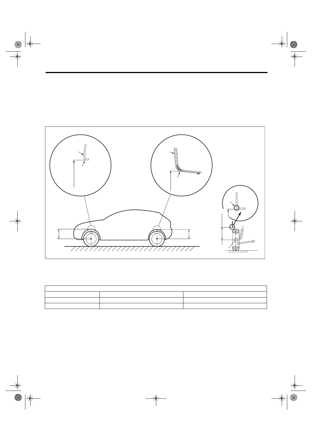
1. WHEEL ARCH HEIGHT
1) Park the vehicle on a level surface.
2) Empty the vehicle so that it is at “curb weight”. (Empty the luggage compartment, load the spare tire, jack
and service tools, and fill up the fuel tank.)
3) Set the steering wheel in a straight-ahead position, and stabilize the suspension by moving the vehicle in
a straight line for 5 m (16 ft) or more.
4) Suspend a thread from the wheel arch (point “A” in the figure (FS-00442)) and affix at a position directly
above the center of wheel.
5) Measure the distance between the point “A” (end of curve) and the center of wheel.
(1)
Wheel arch height
(4)
Front wheel arch height
(7)
Point of measurement
(2)
Front fender
(5)
Rear wheel arch height
(8)
End of spindle
(3)
Rear quarter
(6)
Flange bend line
Wheel arch height specification mm (in) (Tolerance
+12 mm
–24 mm
(
+0.47 in
–0.94 in
))
Model
Except for STI model
STI model
Front
376 (14.8)
371 (14.6)
Rear
370 (14.6)
365 (14.4)
FS-00442
A
A
A
(4)
(1)
(2)
(3)
(1)
(5)
(1)
(7)
(6)
(8)
FS-10
Wheel Alignment
FRONT SUSPENSION
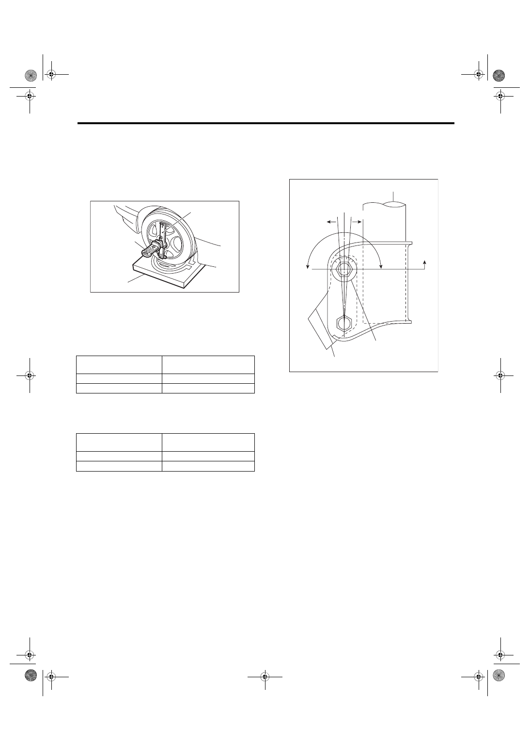
2. CAMBER
• Inspection
1) Place the front wheel on the turning radius
gauge. Make sure the ground contact surfaces of
the front and rear wheels are at the same height.
2) Set the adapter into the center of wheel, and
then set the wheel alignment gauge.
3) Measure the camber angle in accordance with
the operation manual for wheel alignment gauge.
• Front camber adjustment
1) When adjusting the camber, adjust it to the fol-
lowing value.
2) Loosen the two flange nuts located at the front
lower section of the strut.
NOTE:
When the adjusting bolt needs to be loosened or
tightened, hold its head with a wrench and turn the
flange nut.
3) Turn the camber adjusting bolt so that the cam-
ber is set at specification.
NOTE:
Moving the adjusting bolt by one scale changes the
camber by approximately 0°15′.
(1) Alignment gauge
(2) Turning radius gauge
(3) Adapter
Model
Camber (Difference between
RH and LH 45′ or less)
Except for STI model
–0°50′±0°45′
STI model
–0°45′±0°45′
Model
Camber (Difference between
RH and LH 30′ or less)
Except for STI model
–0°50′±0°30′
STI model
–0°45′±0°30′
FS-00213
(1)
(2)
(3)
(1) Strut
(2) Adjusting bolt
(3) Housing
(4) Outer
(5) Inner
(6) Camber is increased.
(7) Camber is decreased.
(1)
(4)
(6)
(7)
(2)
(3)
FS-00008
(5)
Нет комментариевНе стесняйтесь поделиться с нами вашим ценным мнением.
Текст