Subaru Impreza 3 / Impreza WRX / Impreza WRX STI. Service manual — part 403
5MT-33
Switches and Harness
MANUAL TRANSMISSION AND DIFFERENTIAL
7. Switches and Harness
A: REMOVAL
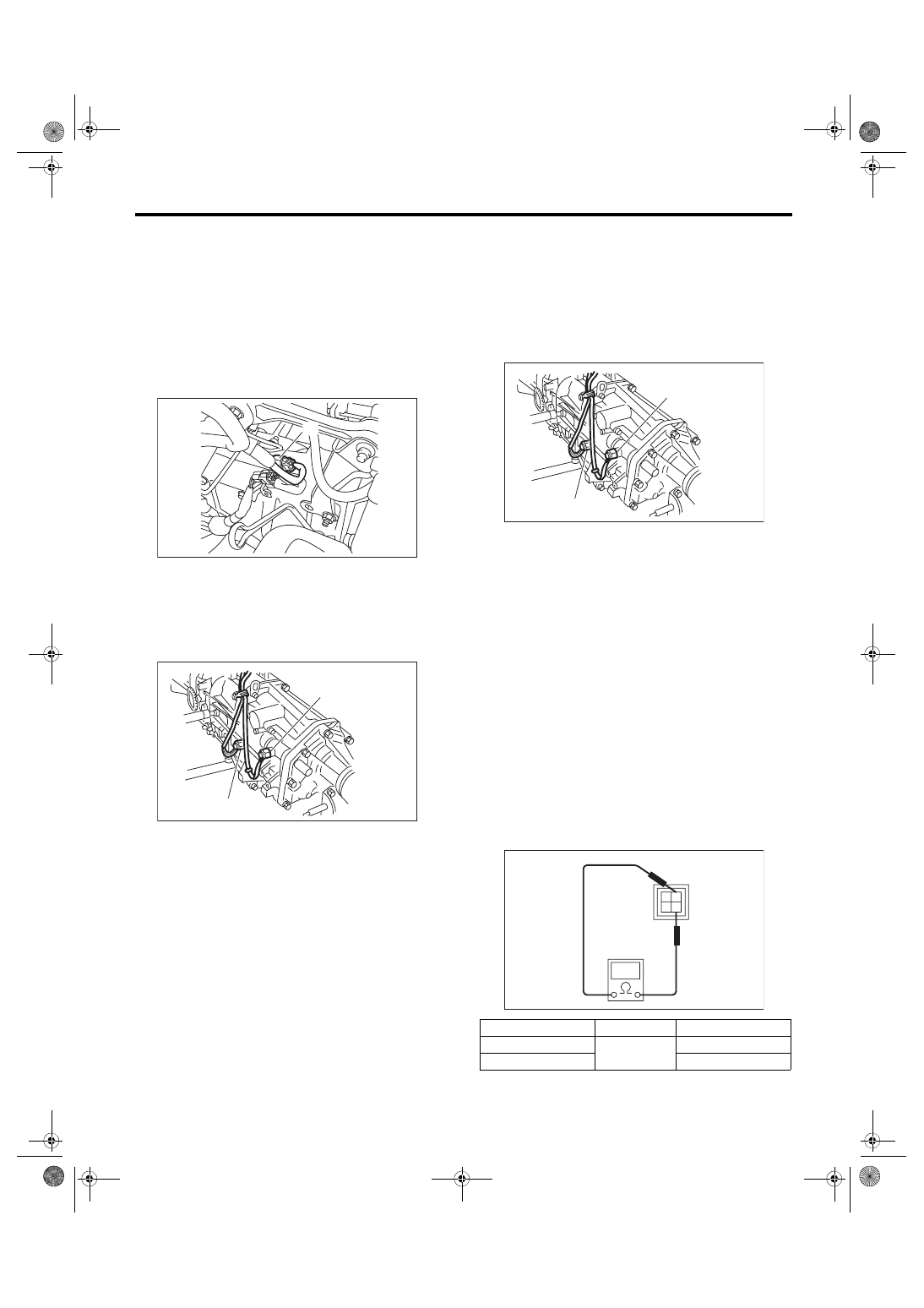
1. BACK-UP LIGHT AND NEUTRAL POSI-
TION SWITCH
1) Disconnect the ground cable from battery.
2) Remove the intercooler. <Ref. to IN(w/o STI)-12,
3) Disconnect the connector back-up light switch &
neutral position switch.
4) Lift up the vehicle.
5) Remove the back-up light switch & neutral posi-
tion switch with the harness.
B: INSTALLATION
1. BACK-UP LIGHT AND NEUTRAL POSI-
TION SWITCH
1) Install the back-up light switch & neutral position
switch with the harness.
Tightening torque:
32.3 N·m (3.3 kgf-m, 23.8 ft-lb)
2) Connect the connectors of back-up light switch &
neutral position switch.
3) Install the intercooler. <Ref. to IN(w/o STI)-12,
4) Connect the battery ground terminal.
C: INSPECTION
1. BACK-UP LIGHT SWITCH
Check the back-up light switch. <Ref. to LI-8, IN-
SPECTION, Back-up Light System.>
2. NEUTRAL POSITION SWITCH
1) Turn the ignition switch to OFF.
2) Disconnect the connector of neutral position
switch.
3) Measure the resistance between neutral posi-
tion switch terminals.
4) Replace faulty parts.
(A) Neutral position switch and back-up light switch
connector
(A) Neutral position switch
(B) Back-up light switch
MT-01659
(A)
MT-02615
(A)
(B)
(A) Neutral position switch
(B) Back-up light switch
Gear shift position
Terminal No.
Specified resistance
Neutral position
1 and 3
Less than 1 Ω
Other positions
1 MΩ or more
MT-02615
(A)
(B)
MT-00111
1
2
3
4
5MT-34
Preparation for Overhaul
MANUAL TRANSMISSION AND DIFFERENTIAL
8. Preparation for Overhaul
A: PROCEDURE
1) Clean oil, grease, dirt and dust from the trans-
mission.
2) Using the TORX
®
bit T70, remove the transmis-
sion gear oil drain plug, and drain the transmission
gear oil completely.
3) Using the TORX
®
bit T70, tighten the transmis-
sion gear oil drain plug.
NOTE:
Use a new gasket.
Tightening torque:
44 N·m (4.5 kgf-m, 32.5 ft-lb) (Aluminum gas-
ket silver)
70 N·m (7.1 kgf-m, 51.6 ft-lb) (Copper gasket
brown)
70 N·m (7.1 kgf-m, 51.6 ft-lb) (Metal gasket
black)
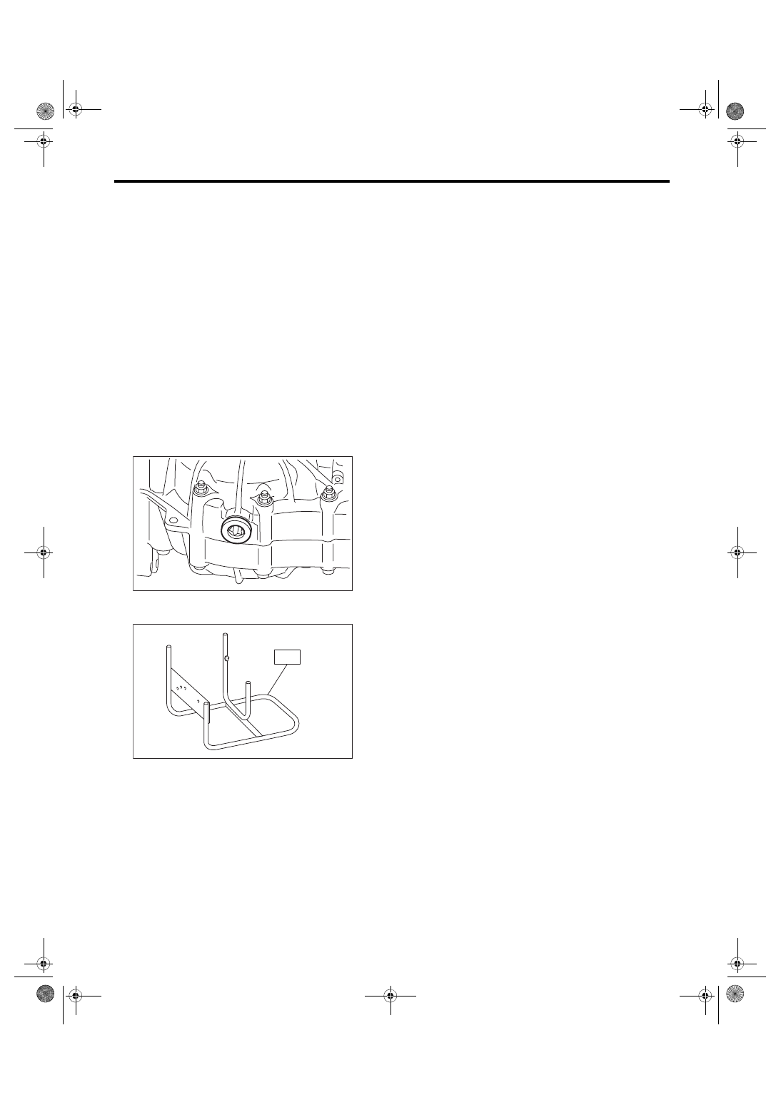
4) Attach the transmission to the ST.
ST 499937100
TRANSMISSION STAND
5) Apply oil to rotating parts before assembly.
6) All disassembled parts, if to be reused, should
be reinstalled in the original positions and direc-
tions.
7) Gaskets, lock washers and lock nuts must be re-
placed with new ones.
8) Apply liquid gasket to the specified areas to pre-
vent leakage.
MT-01548
MT-00115
S T
5MT-35
Transfer Case and Extension Case Assembly
MANUAL TRANSMISSION AND DIFFERENTIAL
9. Transfer Case and Extension
Case Assembly
A: REMOVAL
1) Remove the manual transmission assembly
from the vehicle. <Ref. to 5MT-23, REMOVAL,
Manual Transmission Assembly.>
2) Remove the back-up light switch and the neutral
position switch. <Ref. to 5MT-33, REMOVAL,
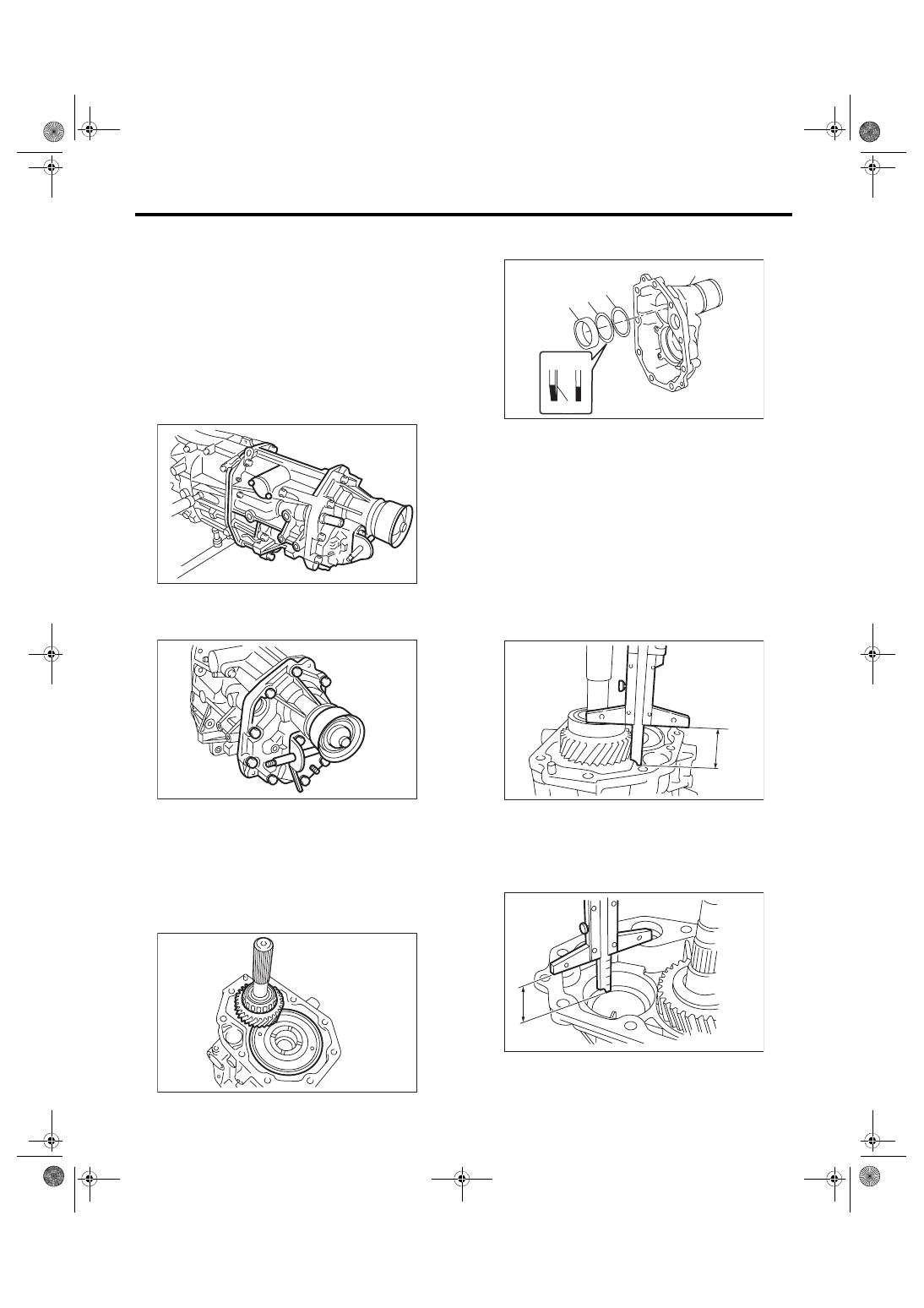
3) Remove the transfer case together with the ex-
tension case assembly.
4) Remove the gasket.
5) Remove the shifter arm.
6) Remove the extension case assembly.
B: INSTALLATION
1) Apply a coat of grease to the front roller bearing
and rear roller bearing of the transfer driven gear.
Grease:
NICHIMOLY N-130 or equivalent
2) Install the center differential and transfer driven
gear into the transfer case.
3) Remove the bearing outer race, dish plate and
adjusting washer from the extension case.
4) Install the bearing outer race to transfer driven
gear.
5) While pressing the bearing outer race horizontal-
ly, rotate the driven shaft for ten turns.
6) Measure the height “W” between transfer case
and taper roller bearing on the transfer driven gear.
7) Measure depth “X” of bearing insertion part of
the extension case.
NOTE:
Measure with bearing outer race, dish plate and ad-
justing washer removed.
MT-02614
MT-00117
MT-00118
(A) Bearing outer race
(B) Dish plate
(C) Thrust washer
(D) Extension case
(1) Paint side
MT-03047
(B)
(C)
(C)
(D)
(B)
(A)
(1)
MT-00120
W
MT-00121
X
5MT-36
Transfer Case and Extension Case Assembly
MANUAL TRANSMISSION AND DIFFERENTIAL
8) Calculate the adjusting washer thickness “t” us-
ing the following calculation.
t = X – W – (1.715 — 1.765 mm (0.0686 — 0.0706
in))
9) Select the washer with the nearest value in the
following table.
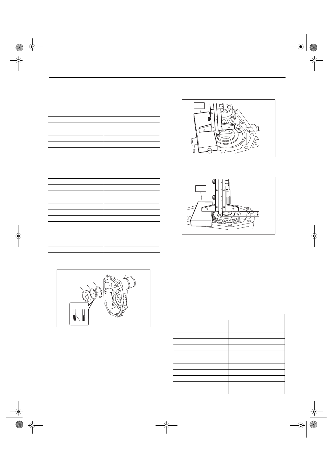
10) Install the selected adjusting washer, dish plate
and bearing outer race (A) into the extension case.
11) Measure the depth “S” between the transfer
case + ST and the center differential.
ST 398643600
GAUGE
12) Measure the height “T” between the extension
case + ST and the transfer drive gear.
ST 398643600
GAUGE
13) Calculate the thrust washer thickness “U” using
the following calculation.
U = S + T – 30 mm (1.18 in) – (0.15 — 0.35 mm
(0.0059 — 0.0138 in))
S: Depth between the transfer case + ST and the
center differential
T: Height between the extension case + ST and the
transfer drive gear
30 mm (1.18 in): Thickness of ST (× 2 pieces)
0.15 — 0.35 mm (0.0059 — 0.0138 in): Clearance
14) Select a suitable washer in the following table.
Standard clearance:
0.15 — 0.35 mm (0.0059 — 0.0138 in)
Adjusting washer (61 × 50 × t)
Part No.
Thickness mm (in)
803050060
0.50 (0.0197)
803050061
0.55 (0.0217)
803050062
0.60 (0.0236)
803050063
0.65 (0.0256)
803050064
0.70 (0.0276)
803050065
0.75 (0.0295)
803050066
0.80 (0.0315)
803050067
0.85 (0.0335)
803050068
0.90 (0.0354)
803050069
0.95 (0.0374)
803050070
1.00 (0.0394)
803050071
1.05 (0.0413)
803050072
1.10 (0.0433)
803050073
1.15 (0.0453)
803050074
1.20 (0.0472)
803050075
1.25 (0.0492)
803050076
1.30 (0.0512)
803050077
1.35 (0.0531)
803050078
1.40 (0.0551)
803050079
1.45 (0.0571)
(A) Bearing outer race
(B) Dish plate
(C) Thrust washer
(D) Extension case
(1) Paint side
MT-03047
(B)
(C)
(C)
(D)
(B)
(A)
(1)
Adjusting washer
Part No.
Thickness mm (in)
803036050
0.9 (0.035)
803036054
1.0 (0.039)
803036051
1.1 (0.043)
803036055
1.2 (0.047)
803036052
1.3 (0.051)
803036056
1.4 (0.055)
803036053
1.5 (0.059)
803036057
1.6 (0.063)
803036058
1.7 (0.067)
803036080
1.8 (0.071)
803036081
1.9 (0.075)
MT-00122
ST
S
MT-00123
T
ST
Нет комментариевНе стесняйтесь поделиться с нами вашим ценным мнением.
Текст