Subaru Impreza 3 / Impreza WRX / Impreza WRX STI. Service manual — part 32
FU(STI)-40
Knock Sensor
FUEL INJECTION (FUEL SYSTEMS)
7. Knock Sensor
A: REMOVAL
1) Disconnect the ground cable from battery.
2) Remove the intercooler. <Ref. to IN(STI)-12,
3) Remove the intake manifold. <Ref. to FU(STI)-
17, REMOVAL, Intake Manifold.>
4) Remove the secondary air combination valve
RH. <Ref. to EC(STI)-29, REMOVAL, Secondary
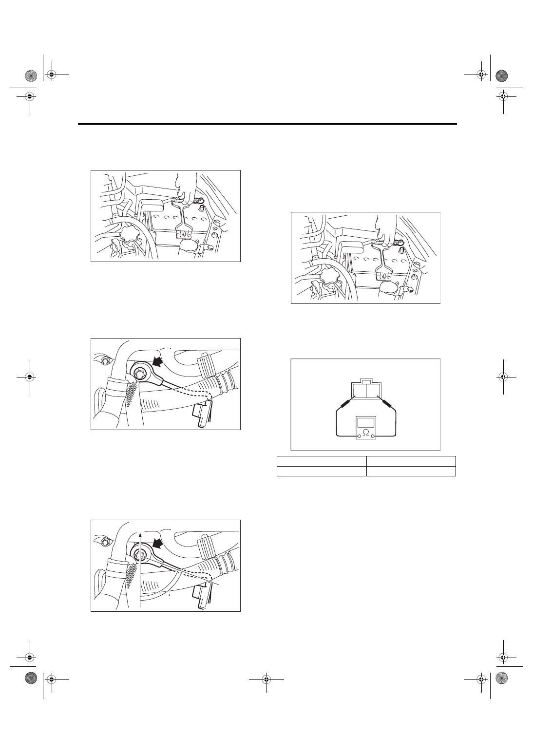
5) Remove the knock sensor from cylinder block.
B: INSTALLATION
1) Install the knock sensor to the cylinder block.
NOTE:
The portion of the knock sensor cord that is pulled
out must be positioned at a 60° angle relative to the
engine rear.
Tightening torque:
24 N·m (2.4 kgf-m, 17.7 ft-lb)
2) Install the secondary air combination valve RH.
<Ref. to EC(STI)-30, SECONDARY AIR COMBI-
NATION VALVE RH, INSTALLATION, Secondary
3) Install the intake manifold. <Ref. to FU(STI)-21,
INSTALLATION, Intake Manifold.>
4) Install the intercooler. <Ref. to IN(STI)-13, IN-
5) Connect the battery ground terminal.
C: INSPECTION
1) Check that the knock sensor has no deforma-
tion, cracks or other damages.
2) Measure the resistance between knock sensor
terminals.
(A) Front side of vehicle
IN-00203
FU-04494
FU-05758
60
(A)
Terminal No.
Standard
1 and 2
560±28 kΩ
IN-00203
2 1
EC-02428
FU(STI)-41
Throttle Position Sensor
FUEL INJECTION (FUEL SYSTEMS)
8. Throttle Position Sensor
A: SPECIFICATION
Throttle body is a non-disassembled part, so do not
remove the throttle position sensor from throttle
body.
Refer to “Throttle Body” for removal and installation
procedure. <Ref. to FU(STI)-15, REMOVAL, Throt-
FU(STI)-42
Mass Air Flow and Intake Air Temperature Sensor
FUEL INJECTION (FUEL SYSTEMS)
9. Mass Air Flow and Intake Air
Temperature Sensor
A: REMOVAL
1) Disconnect the ground cable from battery.
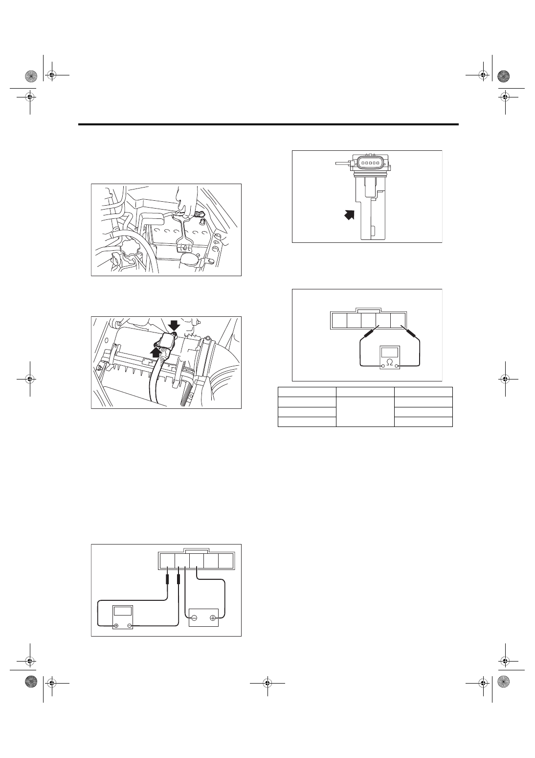
2) Disconnect the connector (A) from the mass air
flow and intake air temperature sensor, and re-
move the mass air flow and intake air temperature
sensor.
B: INSTALLATION
Install in the reverse order of removal.
Tightening torque:
1 N·m (0.1 kgf-m, 0.7 ft-lb)
C: INSPECTION
1. CHECK THE MASS AIR FLOW SENSOR
UNIT
1) Connect the battery positive terminal to terminal
No. 3 and the battery ground terminal to terminal
No. 4, the circuit tester positive terminal to terminal
No. 5 and the circuit tester ground terminal to termi-
nal No. 4.
2) Check the voltage changes when air is blown to
the mass air flow sensor unit in arrow direction.
2. CHECK THE INTAKE AIR TEMPERA-
TURE SENSOR UNIT
Measure the resistance between intake air temper-
ature sensor terminals.
3. OTHER INSPECTIONS
1) Check that the mass air flow and intake air tem-
perature sensor has no deformation, cracks or oth-
er damages.
2) Check that the mass air flow and intake air tem-
perature sensor has no dirt.
IN-00203
FU-05798
(A)
5 4 3 2 1
FU-04062
V
Temperature
Terminal No.
Standard
–20°C (–4°F)
1 and 2
16.0±2.4 kΩ
20°C (68°F)
2.45±0.24 kΩ
60°C (140°F)
0.580±0.087 kΩ
FU-04063
FU-04064
5 4 3 2 1
FU(STI)-43
Manifold Absolute Pressure Sensor
FUEL INJECTION (FUEL SYSTEMS)
10.Manifold Absolute Pressure
Sensor
A: REMOVAL
1) Disconnect the ground cable from battery.
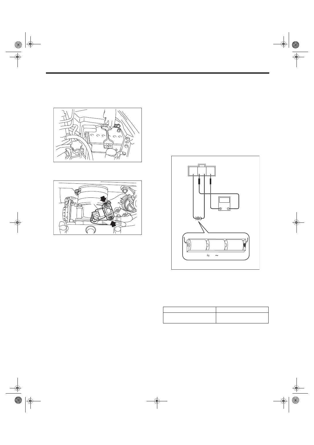
2) Disconnect the connector (A) from the manifold
absolute pressure sensor, and remove the mani-
fold absolute pressure sensor from throttle body.
B: INSTALLATION
Install in the reverse order of removal.
NOTE:
Use new O-rings.
Tightening torque:
2 N·m (0.2 kgf-m, 1.5 ft-lb)
C: INSPECTION
1) Check that the manifold absolute pressure sen-
sor has no deformation, cracks or other damages.
2) Connect dry-cell battery positive terminal to ter-
minal No. 3 and dry-cell battery ground terminal to
terminal No. 2, circuit tester positive terminal to ter-
minal No. 1 and the circuit tester negative terminal
to terminal No. 2.
NOTE:
• Use new dry-cell batteries.
• Using circuit tester, check the voltage of a single
dry-cell battery is 1.6 V or more. And also check the
voltage of three batteries in series is between 4.8 V
and 5.2 V.
3) Check the voltage at a normal atmospheric pres-
sure.
NOTE:
The atmospheric pressure at higher altitude is low-
er than normal. Therefore, the voltage is lower than
the standard value.
IN-00203
FU-05799
(A)
Terminal No.
Standard
1 (+) and 2 (–)
Approx. 2.0 V
(when 25°C (77°F))
FU-04491
V
3 2 1
1.5V
1.5V
1.5V
4.8 5.2V
Нет комментариевНе стесняйтесь поделиться с нами вашим ценным мнением.
Текст