Subaru Legacy (2005 year). Service manual — part 1041
LAN(diag)-43
LAN SYSTEM (DIAGNOSTICS)
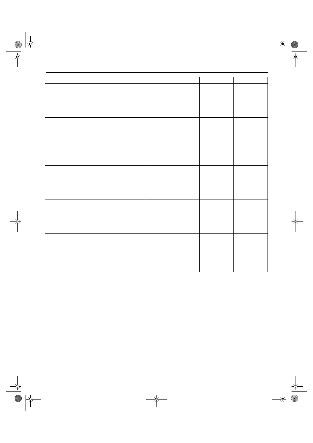
Diagnostic Procedure with Diagnostic Trouble Code (DTC)
Step
Check
Yes
No
1
CHECK HARNESS.
1) Disconnect the body integrated module
connector.
2) Measure the resistance between body inte-
grated module connector and chassis ground.
Connector & terminal
(B280) No. 6 — Chassis ground:
Is the resistance 10 — 30
Ω?
2
CHECK HARNESS.
1) Disconnect the body integrated module
connector.
2) Disconnect the shift lock solenoid connec-
tor.
3) Measure the resistance between body inte-
grated module connector and shift lock sole-
noid connector.
Connector & terminal
(B280) No. 6 — (B116) No. 3:
Is the resistance less than 10
Ω?
Repair or replace
the open or short
circuit of harness.
3
CHECK SHIFT LOCK SOLENOID.
1) Disconnect the shift lock solenoid connec-
tor.
2) Measure the internal resistance of shift lock
solenoid.
Connector & terminal
(B116) No. 3 — No. 4:
Is the resistance 10 — 30
Ω?
Replace the shift
lock solenoid.
4
CHECK GROUND CIRCUIT.
1) Disconnect the shift lock solenoid connec-
tor.
2) Measure the resistance between shift lock
solenoid connector and chassis ground.
Connector & terminal
(B116) No. 4 — Chassis ground:
Is the resistance less than 10
Ω?
Temporary poor
contact occurs.
Check the connec-
tion of each termi-
nals, and then
repair them if nec-
essary.
Replace the body
integrated mod-
ule. <Ref. to SL-
44, Body Inte-
grated Module.>
5
CHECK HARNESS.
1) Disconnect both the body integrated mod-
ule connector and shift lock solenoid connector
(B116).
2) Measure the resistance between body inte-
grated module connector and chassis ground.
Connector & terminal
(B280) No. 6 — Chassis ground:
Is the resistance more than 1
M
Ω?
Replace the body
integrated mod-
ule. <Ref. to SL-
44, Body Inte-
grated Module.>
Repair or replace
the short circuit of
harness.
LAN(diag)-44
LAN SYSTEM (DIAGNOSTICS)
Diagnostic Procedure with Diagnostic Trouble Code (DTC)
I:
DTC B0107 R FOG LAMP CIRCUIT FAILURE
DTC DETECTING CONDITION:
Rear fog input/output circuits are ground shorted.
TROUBLE SYMPTOM:
• Rear fog light does not come on or go off.
• Indicator in the combination meter may not go off.
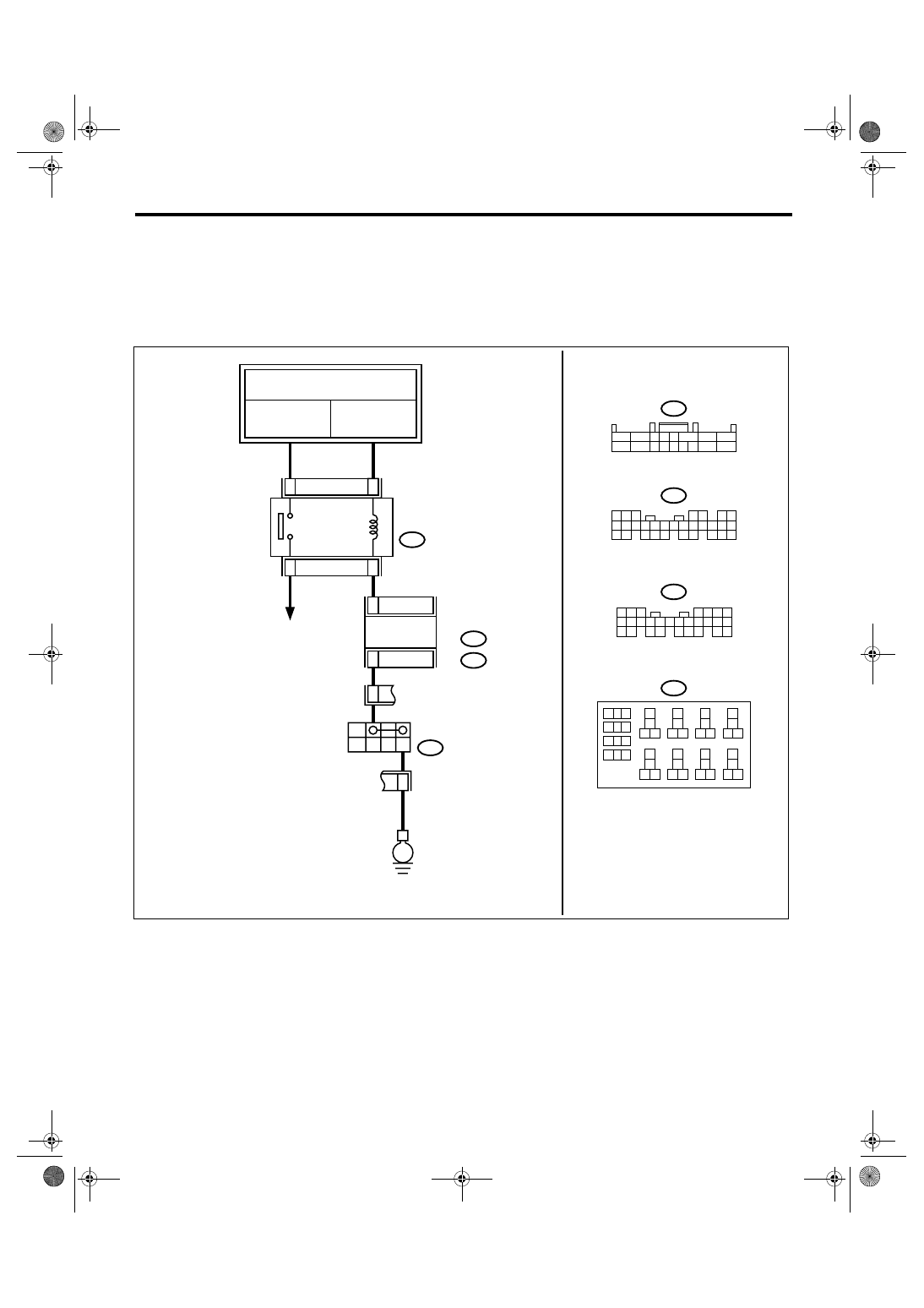
WIRING DIAGRAM:
LAN00158
FB-2
F/B FUSE No.1
(B)
REF.TO POWER SUPPLY ROUTING
FB-14
F/B FUSE No.16
(B)
26
28
25
27
B13
C4
ON
OFF
E
13
16
B225
REAR FOG
LIGHT RELAY
REAR FOG LIGHT
B71
REAR FOG
LIGHT SWITCH
9
10
1
2
3
4
5
6
7
8
11 12
14
15 16
13
18
19 20
17
22
23 24
21
38
39 40
37
34
35 36
33
30
31 32
29
26
27 28
25
B225
2
3 4 5
6
7
1
8
9
10
11 12 13 14 15
16
17
B71
B280
B281
BODY
INTEGRATED
MODULE
B:
C:
5 6 7
8
2
1
9
4
3
10
24
22 23
25
11 12 13 14 15
26
27 28
16 17 18 19
20 21
B281
5
4
6 7
8
2
1
9
3
10
22
23
11 12 13 14 15
24 25
26 27
16 17 18
28 29
19 20
21
30
B280
B:
C:
LAN(diag)-45
LAN SYSTEM (DIAGNOSTICS)
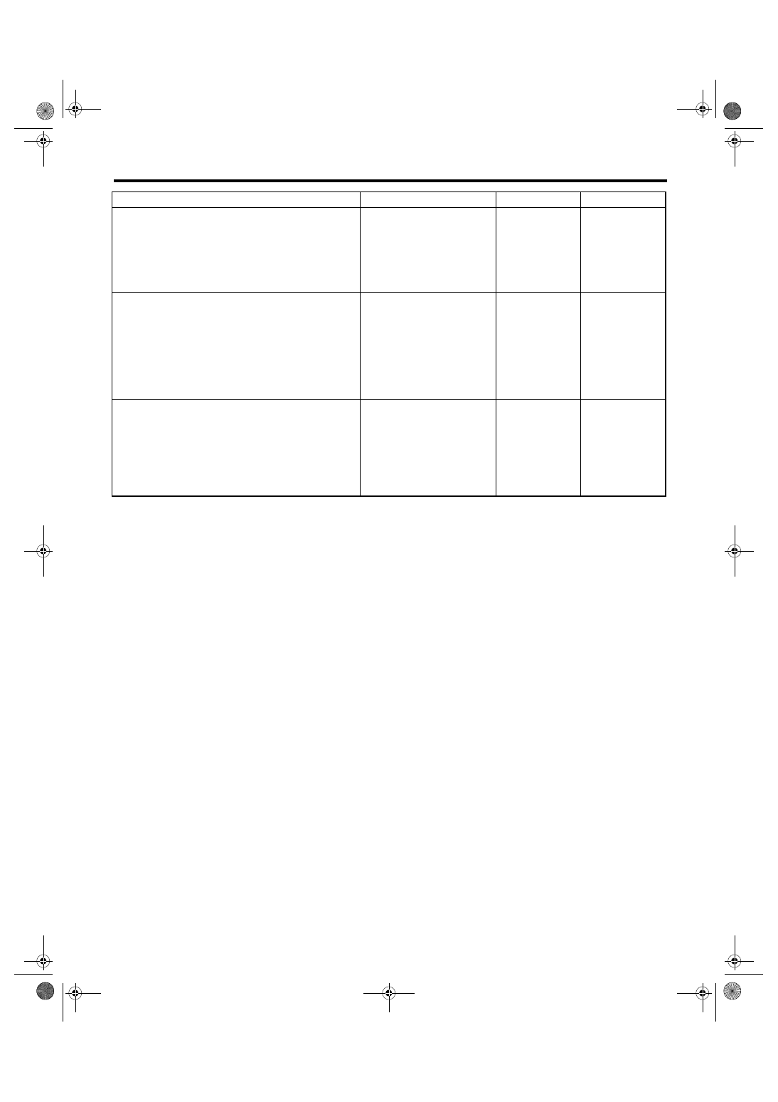
Diagnostic Procedure with Diagnostic Trouble Code (DTC)
Step
Check
Yes
No
1
CHECK HARNESS.
1) Disconnect the body integrated module
connector.
2) Measure the voltage between body inte-
grated module connector and chassis ground.
Connector & terminal
(B280) No. 13 (+) — Chassis ground (
−
):
Is the voltage 10 — 13 V?
Temporary poor
contact.
2
CHECK HARNESS.
1) Disconnect the body integrated module
connector.
2) Disconnect the rear fog light relay.
3) Measure the resistance between body inte-
grated module connector and rear fog light
relay connector.
Connector & terminal
(B280) No. 13 — (B225) No. 27:
Is the resistance less than 1
Ω?
Repair the open or
short circuit of har-
ness.
3
CHECK HARNESS.
1) Disconnect the body integrated module
connector.
2) Disconnect the rear fog light relay.
3) Measure the resistance between body inte-
grated module connector and chassis ground.
Connector & terminal
(B280) No. 13 — Chassis ground:
Is the resistance more than 1
M
Ω?
Replace the body
integrated mod-
ule. <Ref. to SL-
44, Body Inte-
grated Module.>
Repair or replace
the short circuit of
harness.
LAN(diag)-46
LAN SYSTEM (DIAGNOSTICS)
Diagnostic Procedure with Diagnostic Trouble Code (DTC)
J: DTC B0201 CAN-HS COUNTER ABNORMAL
DTC DETECTING CONDITION:
High speed CAN communication of body integrated module which monitor the error data and non-received
data are faulty.
TROUBLE SYMPTOM:
• “Er HC” is displayed in odo/trip meter.
• Malfunction indicator light illuminates.
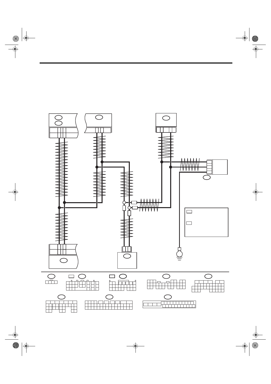
WIRING DIAGRAM:
LAN00174
VDCCM & H/U
B310
B301
4 5 6 7 8 9
16 17 18 19 20
2 3
1
21 22 23 24 25 26
10 11
13
14
12
15
B20
B30
TWISTED WIRE
BODY INTEGRATED
MODULE
B280
B:
A12
A3
TCM
B54
A:
11
26
B301
ABSCM & H/U
13
29
B231
2
1
3
STEERING ANGLE
SENSOR
ABS
ABS
VDC
VDC
B231
1 2 3 4
B54
A:
1 2
7
8
9
5 6
3 4
10 11 12
19 20 21
13
14 15
16
17
18
22
23
24
B137
D:
8
5
6
10 11 12 13 14 15
7
2
1
3
4
16
30
19 20
22
28 29
9
17
18
25
21
23
24
31
26 27
B310
1 2 3 4
11 12
14 15 16 17 18 19 20 21 22 23 24 25
10
26
27 28 29 30 31 32 33 34 35 36 37 38 39 40 41 42
13
7
8
6
5
9
B280
B:
5
4
6 7
8
2
1
9
3
10
22
23
11 12 13 14 15
24 25
26 27
16 17 18
28 29
19 20
21
30
ECM
B137
D:
C14
C13
A3
A4
D26
D18
5AT
4AT
E
5AT
B54
1 2
7
8 9
5
6
3
4
10 11 12
19 20 21
13 14 15 16
17 18
22 23 24
4AT A:
B136
C:
*
1
*
2
B136
5
6
7 8
2
1
9
4
3
10
24
22 23
25
11 12 13 14 15
26 27
28
16
17 18 19 20 21
33 34
29
32
30
31
35
C:
1
*
: 2.0 L SOHC RHD MODEL;
2.5 L (KA) RHD MODEL;
2.0 L LHD MODEL;
2.5 L (KS) LHD MODEL
2
*
: EXCEPT FOR 2.0 L SOHC
RHD AND 2.5 L (KA) RHD
MODEL;
2.5 L (EC, K4) LHD MODEL;
3.0 L LHD MODEL
Нет комментариевНе стесняйтесь поделиться с нами вашим ценным мнением.
Текст