Subaru Legacy (2005 year). Service manual — part 1042
LAN(diag)-47
LAN SYSTEM (DIAGNOSTICS)
Diagnostic Procedure with Diagnostic Trouble Code (DTC)
Step
Check
Yes
No
1
CHECK HARNESS.
1) Disconnect the body integrated module
connector.
2) Measure the resistance between body inte-
grated module connector terminals.
Connector & terminal
(B280) No. 20 — No. 30:
Is the resistance 55 — 65
Ω?
2
CHECK HARNESS.
Measure the resistance between body inte-
grated module connector terminals.
Connector & terminal
(B280) No. 20 — No. 30:
Is the resistance less than 10
Ω?
3
CHECK HARNESS.
Measure the resistance between body inte-
grated module connector terminals.
Connector & terminal
(B280) No. 20 — No. 30:
Is the resistance 110 — 130
Ω?
4
CHECK HARNESS.
Measure the resistance between body inte-
grated module connector terminals.
Connector & terminal
(B280) No. 20 — No. 30:
Is the resistance more than 30
M
Ω?
Repair or replace
the short circuit of
harness of body
integrated module.
5
CHECK HARNESS.
Measure the harness resistance between the
body integrated module connector and chassis
ground.
Connector & terminal
(B280) No. 20 — Chassis ground:
Is the resistance less than 10
Ω?
Repair or replace
the ground short
circuit of harness.
6
CHECK HARNESS.
Measure the harness resistance between the
body integrated module connector and chassis
ground.
Connector & terminal
(B280) No. 30 — Chassis ground:
Is the resistance less than 10
Ω?
Repair or replace
the ground short
circuit of harness.
7
CHECK HARNESS.
1) Turn the ignition switch to ON.
2) Measure the voltage between body inte-
grated module connector and chassis ground.
Connector & terminal
(B280) No. 20 (+) — Chassis ground (
−
):
Is the voltage more than 6 V?
8
CHECK HARNESS.
1) Turn the ignition switch to ON.
2) Measure the voltage between body inte-
grated module connector and chassis ground.
Connector & terminal
(B280) No. 30 (+) — Chassis ground (
−
):
Is the voltage more than 6 V?
9
CHECK CONTROL MODULE (EXCEPT FOR
VDC MODEL, GO TO NEXT).
1) Connect the body integrated module con-
nector.
2) Perform the clear memory mode.
3) Disconnect the steering angle sensor con-
nector (B231), and read the DTC. <Ref. to
LAN(diag)-14, READ DIAGNOSTIC TROUBLE
CODE (DTC), OPERATION, Subaru Select
Monitor.>
Is DTC B0201 displayed on
Subaru Select Monitor?
Replace the steer-
ing angle sensor.
<Ref. to VDC-17,
REPLACEMENT,
Steering Angle
Sensor.>
LAN(diag)-48
LAN SYSTEM (DIAGNOSTICS)
Diagnostic Procedure with Diagnostic Trouble Code (DTC)
10
CHECK CONTROL MODULE (EXCEPT FOR
AT MODEL, GO TO NEXT).
1) Connect the steering angle sensor connec-
tor.
2) Perform the clear memory mode.
3) Disconnect the TCM connector (B54), and
read the DTC.
Is DTC B0201 displayed on
Subaru Select Monitor?
Replace the TCM.
<Ref. to 5AT-61,
REMOVAL, Trans-
mission Control
Module (TCM).>
11
CHECK CONTROL MODULE.
1) Connect the TCM connector.
2) Perform the clear memory mode.
3) Disconnect the VDC/ABS connector (B310
or B301), and read the DTC.
Is DTC B0201 displayed on
Subaru Select Monitor?
12
CHECK ECM.
1) Connect all the control module connectors.
2) Check the data of “Integ. unit data
received” on the current data display of ECM.
Is the “Yes” displayed?
Replace the body
integrated mod-
ule. <Ref. to SL-
44, REMOVAL,
Body Integrated
Module.>
13
CHECK BODY INTEGRATED MODULE.
Check the data of “body integrated module
counter update” on ECM data display using
Subaru Select Monitor.
Is the “Yes” displayed?
Replace the body
integrated mod-
ule. <Ref. to SL-
44, REMOVAL,
Body Integrated
Module.>
14
CHECK HARNESS.
1) Disconnect the body integrated module
connector.
2) Measure the resistance between body inte-
grated module connector terminals.
3) Disconnect the connectors of each control
unit.
Connector & terminal
(B280) No. 20 — No. 30:
Is there any control module
which its resistance changes
from less than 10
Ω?
Replace the con-
trol module which
its resistance
changes.
Repair or replace
the short circuit of
the harness.
Step
Check
Yes
No
LAN(diag)-49
LAN SYSTEM (DIAGNOSTICS)
Diagnostic Procedure with Diagnostic Trouble Code (DTC)
15
CHECK HARNESS.
1) Disconnect the VDC/ABSCM connector.
2) Measure the resistance between body inte-
grated module connector terminals.
Connector & terminal
(B280) No. 20 — No. 30:
Is the resistance more than 30
M
Ω?
Replace the VDC/
ABSCM. <Ref. to
VDC-7,
REMOVAL, VDC
Control Module
and Hydraulic
Control Unit
(VDCCM&H/U).>
<Ref. to ABS-6,
REMOVAL, ABS
Control Module
and Hydraulic
Control Unit
(ABSCM&H/U).>
16
CHECK HARNESS.
1) Connect the VDC/ABSCM connector, and
disconnect the ECM connector (B136 or
B137).
2) Measure the resistance between body inte-
grated module connector terminals.
Connector & terminal
(B280) No. 20 — No. 30:
Is the resistance more than 30
M
Ω?
Replace the ECM. Go to step 17.
17
CHECK HARNESS.
1) Disconnect all the control module (body
integrated module, ECM, TCM, VDC/ABS and
steering angle sensor).
2) Measure the resistance between body inte-
grated module connector terminals.
Connector & terminal
(B280) No. 20 — No. 30:
Is the resistance more than 30
M
Ω?
Temporary poor
contact occurs.
Repair or replace
the short circuit of
the harness.
18
CHECK HARNESS.
1) Measure the voltage between body inte-
grated module connector terminals.
2) Turn the ignition switch to ON, and discon-
nect the unit connectors in order. (TCM: B54,
VDC/ABS: B310, B301, ECM: B137, B136,
Steering angle sensor: B231)
Connector & terminal
(B280) No. 20 (+) — Chassis ground (
−
):
When disconnecting, is there
any module which its voltage
decreases from 6 V or more?
Replace the mod-
ule which its volt-
age changes.
Repair or replace
the short circuit of
the harness.
19
CHECK HARNESS.
1) Measure the voltage between body inte-
grated module connector terminals.
2) Turn the ignition switch to ON, and discon-
nect the unit connectors in order. (TCM: B54,
VDC/ABS: B310, B301, ECM: B137, B136,
Steering angle sensor: B231)
Connector & terminal
(B280) No. 30 (+) — Chassis ground (
−
):
When disconnecting, is there
any module which its voltage
decreases from 6 V or more?
Replace the mod-
ule which its volt-
age changes.
Repair or replace
the short circuit of
the harness.
Step
Check
Yes
No
LAN(diag)-50
LAN SYSTEM (DIAGNOSTICS)
Diagnostic Procedure with Diagnostic Trouble Code (DTC)
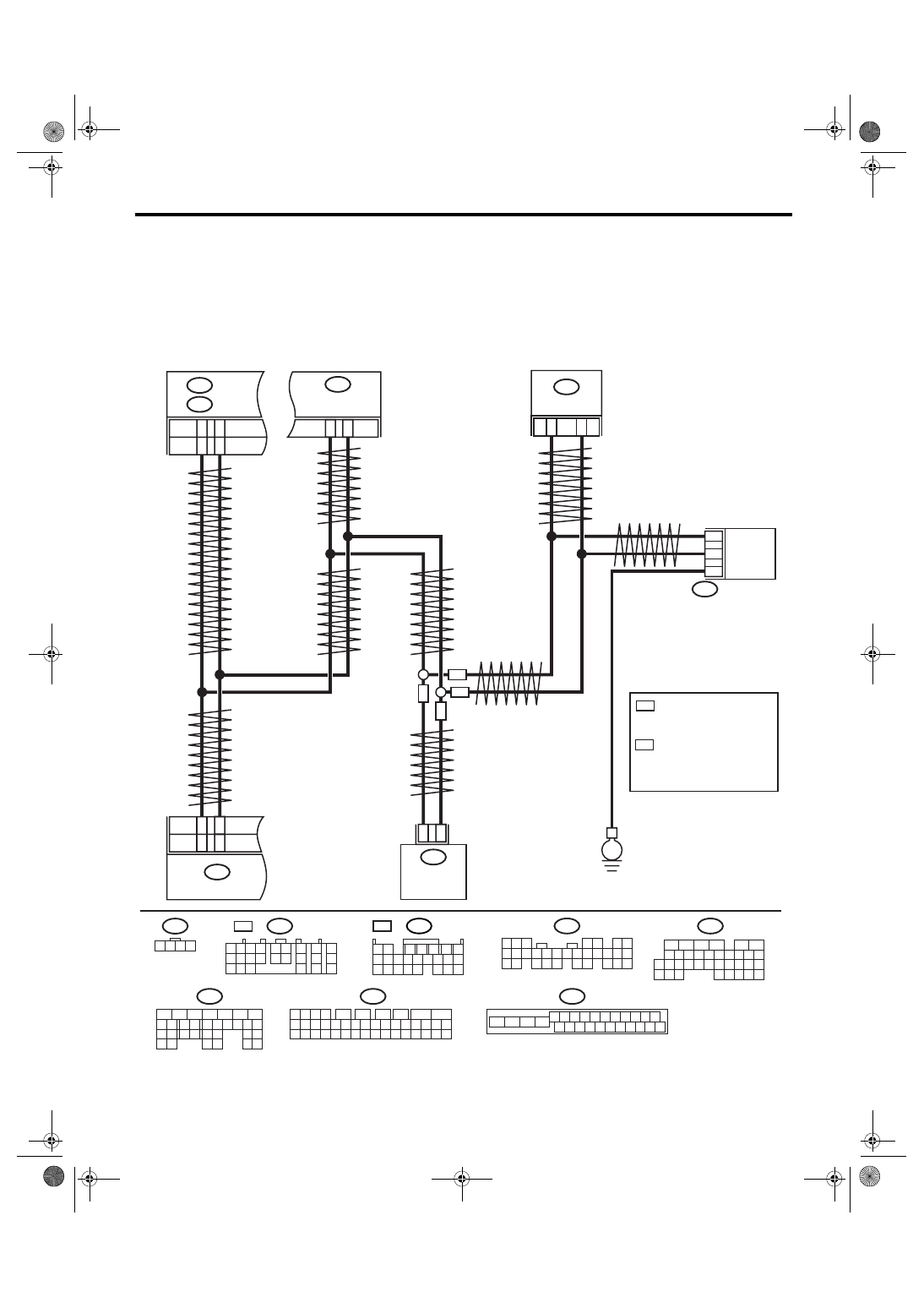
K: DTC B0202 CAN-HS BUS OFF
DTC DETECTING CONDITION:
• Find the unit or CAN line in which trouble occurs, and repair and replace it.
• Not received data and error data may be detected at the same time.
TROUBLE SYMPTOM:
“Er HC” is displayed in odo/trip meter.
WIRING DIAGRAM:
LAN00174
VDCCM & H/U
B310
B301
4 5 6 7 8 9
16 17 18 19 20
2 3
1
21 22 23 24 25 26
10 11
13
14
12
15
B20
B30
TWISTED WIRE
BODY INTEGRATED
MODULE
B280
B:
A12
A3
TCM
B54
A:
11
26
B301
ABSCM & H/U
13
29
B231
2
1
3
STEERING ANGLE
SENSOR
ABS
ABS
VDC
VDC
B231
1 2 3 4
B54
A:
1 2
7
8
9
5 6
3 4
10 11 12
19 20 21
13
14 15
16
17
18
22
23
24
B137
D:
8
5
6
10 11 12 13 14 15
7
2
1
3
4
16
30
19 20
22
28 29
9
17
18
25
21
23
24
31
26 27
B310
1 2 3 4
11 12
14 15 16 17 18 19 20 21 22 23 24 25
10
26
27 28 29 30 31 32 33 34 35 36 37 38 39 40 41 42
13
7
8
6
5
9
B280
B:
5
4
6 7
8
2
1
9
3
10
22
23
11 12 13 14 15
24 25
26 27
16 17 18
28 29
19 20
21
30
ECM
B137
D:
C14
C13
A3
A4
D26
D18
5AT
4AT
E
5AT
B54
1 2
7
8 9
5
6
3
4
10 11 12
19 20 21
13 14 15 16
17 18
22 23 24
4AT A:
B136
C:
*
1
*
2
B136
5
6
7 8
2
1
9
4
3
10
24
22 23
25
11 12 13 14 15
26 27
28
16
17 18 19 20 21
33 34
29
32
30
31
35
C:
1
*
: 2.0 L SOHC RHD MODEL;
2.5 L (KA) RHD MODEL;
2.0 L LHD MODEL;
2.5 L (KS) LHD MODEL
2
*
: EXCEPT FOR 2.0 L SOHC
RHD AND 2.5 L (KA) RHD
MODEL;
2.5 L (EC, K4) LHD MODEL;
3.0 L LHD MODEL
Нет комментариевНе стесняйтесь поделиться с нами вашим ценным мнением.
Текст