Subaru Legacy (2005 year). Service manual — part 1039

LAN(diag)-35
LAN SYSTEM (DIAGNOSTICS)
Diagnostic Procedure with Diagnostic Trouble Code (DTC)
Step
Check
Yes
No
1
CHECK FUSE.
1) Turn the ignition switch to OFF.
2) Remove the fuse (No. 7).
Is the fuse blown out?
Replace the fuse
(No. 7). If the
replaced fuse has
blown out easily,
repair the short cir-
cuit of harness
between fuse (No.
7) and body inte-
grated module.
2
CONTINUITY CHECK OF WIRING HAR-
NESS.
1) Disconnect the connector from body inte-
grated module.
2) Measure the voltage between body inte-
grated module connector and chassis ground.
Connector & terminal
(B281) No. 2 (+) — Chassis ground (
−
):
Is the voltage more than 10 V? Go to step 3.
Repair the har-
ness for open or
shorted circuit
between body inte-
grated module and
fuse.
3
CHECK POOR CONTACT IN CONNECTORS. Is there poor contact in body
integrated module connector?
Repair the poor
contact connector.
4
CHECK BODY INTEGRATED MODULE HAR-
NESS.
1) Connect all the connectors.
2) Perform the clear memory mode.
3) Read DTC.
Is the same DTC displayed on
Subaru Select Monitor?
Replace the body
integrated mod-
ule. <Ref. to SL-
44, Body Inte-
grated Module.>
Temporary poor
contact occurs.
LAN(diag)-36
LAN SYSTEM (DIAGNOSTICS)
Diagnostic Procedure with Diagnostic Trouble Code (DTC)
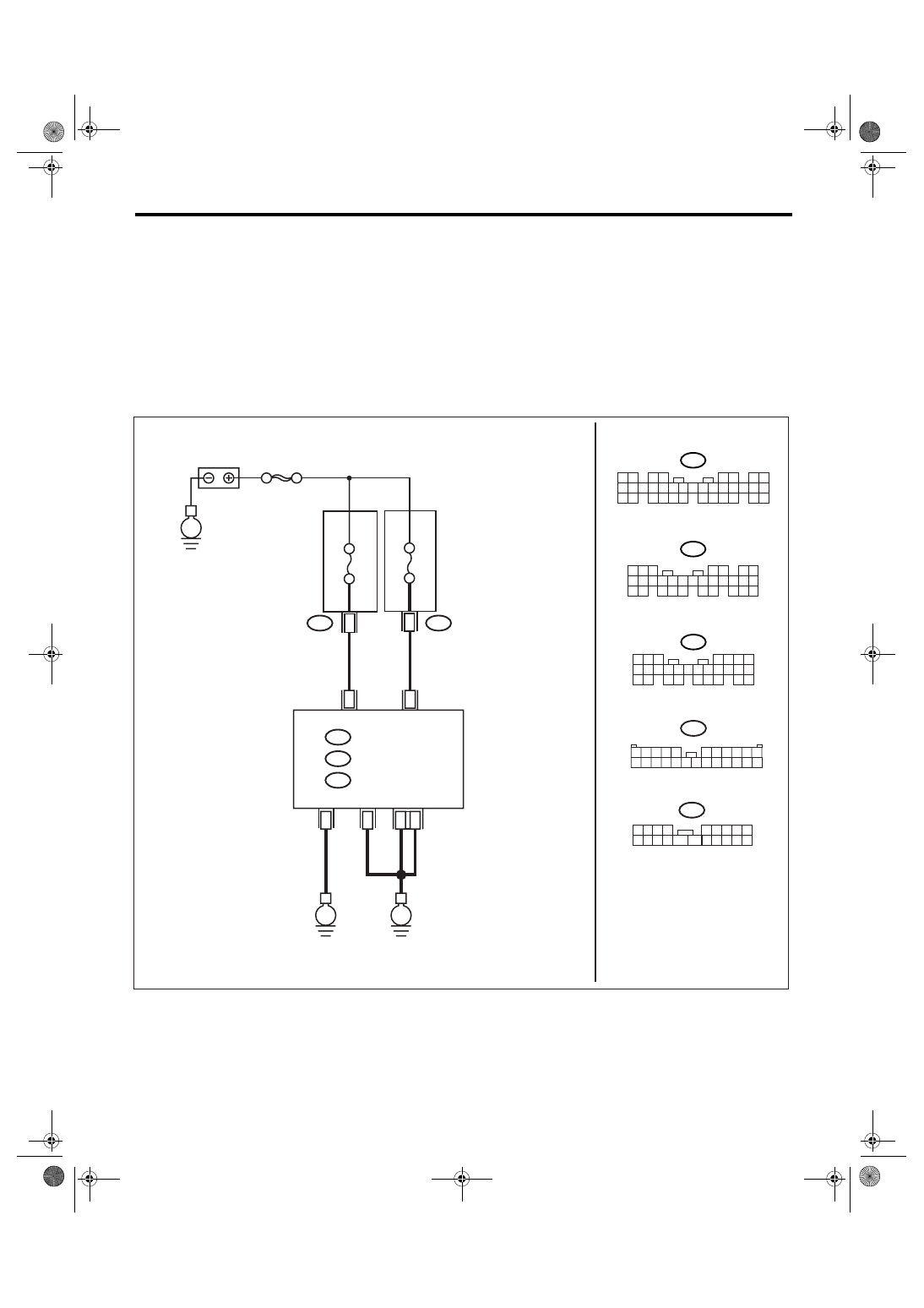
E: DTC B0102 BATT P/SUPPLY MALFUNCTION CONT.
DTC DETECTING CONDITION:
Battery power backup circuit is open or shorted.
TROUBLE SYMPTOM:
• Malfunction indicator light may illuminates.
• Keyless entry, room light and key illumination do not operate.
• “En IU” may display in combination meter.
NOTE:
When some B0101 BATT p/supply malfunction cont. are output at the same time, all function of body inte-
grated module may not function.
WIRING DIAGRAM:
LAN00171
B7
C2
A21
C9
B22
C8
24
13
i84
B52
B280
R168
B:
A:
1 2 3 4
5 6 7 8 9
10 11 12
19 20
13 14 15 16 17 18
R168
B52
3 4
1 2
8 9 10 11
12 13 14 15 16 17 18 19 20 21 22 23 24
5
6 7
E
MAIN SBF
FB-18 No.7
B281
C:
E
E
B280
B:
B281
C:
5 6 7
8
2
1
9
4
3
10
24
22 23
25
11 12 13 14 15
26
27 28
16 17 18 19
20 21
5
4
6 7
8
2
1
9
3
10
22
23
11 12 13 14 15
24 25
26 27
16 17 18
28 29
19 20
21
30
i84
A:
1 2
3 4
5 6
7 8
9 10 11 12 13 14 15 16 17 18 19 20 21 22 23
24 25
26 27 28 29
30 31 32 33
34 35
BATTERY
BODY INTEGRATED
MODULE
B
A
CK-UP
PO
WER SUPPL
Y
SYSTEM CONTR
OL
PO
WER SUPPL
Y
MB-29 No.8
MAIN FUSE BOX
FUSE & RELAY BOX
LAN(diag)-37
LAN SYSTEM (DIAGNOSTICS)
Diagnostic Procedure with Diagnostic Trouble Code (DTC)
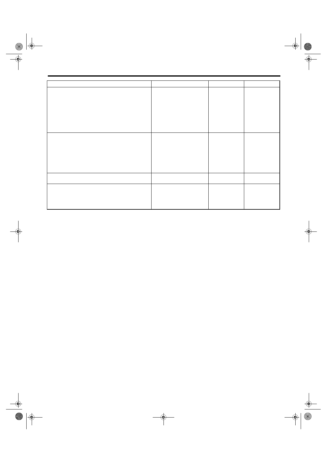
Step
Check
Yes
No
1
CHECK FUSE.
1) Turn the ignition switch to OFF.
2) Remove the fuse (No. 8).
Is the fuse blown out?
Replace the fuse
(No. 8). If the
replaced fuse has
blown out easily,
repair the short cir-
cuit of harness
between fuse (No.
8) and body inte-
grated module.
2
CONTINUITY CHECK OF WIRING HAR-
NESS.
1) Disconnect the connector from body inte-
grated module.
2) Measure the voltage between body inte-
grated module connector and chassis ground.
Connector & terminal
(B280) No. 7 (+) — Chassis ground (
−
):
Is the voltage more than 10 V? Go to step 3.
Repair the har-
ness for open or
shorted circuit
between body inte-
grated module and
fuse.
3
CHECK POOR CONTACT IN CONNECTORS. Is there poor contact in body
integrated module connector?
Repair the poor
contact connector.
4
CHECK BODY INTEGRATED MODULE HAR-
NESS.
1) Connect all the connectors.
2) Perform the clear memory mode.
3) Read DTC.
Is the same DTC displayed on
Subaru Select Monitor?
Replace the body
integrated mod-
ule. <Ref. to SL-
44, Body Inte-
grated Module.>
Temporary poor
contact occurs.
LAN(diag)-38
LAN SYSTEM (DIAGNOSTICS)
Diagnostic Procedure with Diagnostic Trouble Code (DTC)
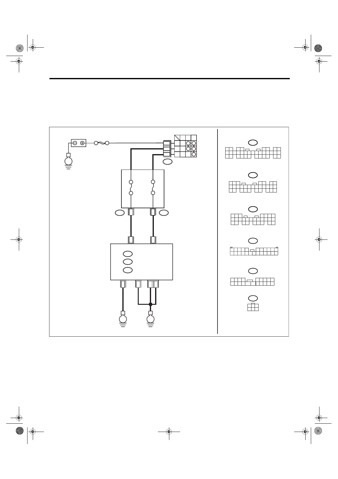
F: DTC B0103 IGNITION POWER FAILURE
DTC DETECTING CONDITION:
IGN power supply circuit is open or shorted.
TROUBLE SYMPTOM:
Symptoms such as illuminating the malfunction indicator light or high speed CAN error display “Er HC” may
occur.
WIRING DIAGRAM:
LAN00172
A1
A24
1
8
B72
1
B
2
4
ACC
ACC
OFF
IG
ON
B52
3 4
1 2
8 9 10 11
12 13 14 15 16 17 18 19 20 21 22 23 24
5
6 7
B280
B:
B281
C:
5 6 7
8
2
1
9
4
3
10
24
22 23
25
11 12 13 14 15
26
27 28
16 17 18 19
20 21
5
4
6 7
8
2
1
9
3
10
22
23
11 12 13 14 15
24 25
26 27
16 17 18
28 29
19 20
21
30
i84
A:
1 2
3 4
5 6
7 8
9 10 11 12 13 14 15 16 17 18 19 20 21 22 23
24 25
26 27 28 29
30 31 32 33
34 35
1 2 3 4
5 6 7 8 9
10 11 12
19 20
13 14 15 16 17 18
i5
B52
i5
E
MAIN SBF
FB-28 No.31
i84
B280
B:
A:
B281
C:
BATTERY
BODY INTEGRATED
MODULE
A
CC PO
WER SUPPL
Y
IG PO
WER SUPPL
Y
IGNITION SWITCH
A21
C9
B22
C8
E
E
FB-37 No.12
1
3
4 5 6
2
B72
FUSE & RELAY BOX
Нет комментариевНе стесняйтесь поделиться с нами вашим ценным мнением.
Текст