Subaru Legacy (2005 year). Service manual — part 1040
LAN(diag)-39
LAN SYSTEM (DIAGNOSTICS)
Diagnostic Procedure with Diagnostic Trouble Code (DTC)
Step
Check
Yes
No
1
CHECK FUSE.
1) Turn the ignition switch to OFF.
2) Remove the fuse (No. 12).
Is the fuse blown out?
Replace the fuse
(No. 12). If the
replaced fuse has
blown out easily,
repair the short cir-
cuit of harness
between fuse (No.
12) and body inte-
grated module.
2
CONTINUITY CHECK OF WIRING HAR-
NESS.
1) Disconnect the connector from body inte-
grated module.
2) Turn the ignition switch to ON.
3) Measure the voltage between body inte-
grated module connector and chassis ground.
Connector & terminal
(i84) No. 1 (+) — Chassis ground (
−
):
Is the voltage more than 10 V? Go to step 3.
Repair the har-
ness for open or
shorted circuit
between body inte-
grated module and
fuse.
3
CHECK POOR CONTACT IN CONNECTOR. Is there poor contact in body
integrated module connector?
Repair the poor
contact connector.
4
CHECK BODY INTEGRATED MODULE HAR-
NESS.
1) Connect all the connectors.
2) Perform the clear memory mode.
3) Read DTC.
Is the same DTC displayed on
Subaru Select Monitor?
Replace the body
integrated mod-
ule. <Ref. to SL-
44, Body Inte-
grated Module.>
Temporary poor
contact occurs.
LAN(diag)-40
LAN SYSTEM (DIAGNOSTICS)
Diagnostic Procedure with Diagnostic Trouble Code (DTC)
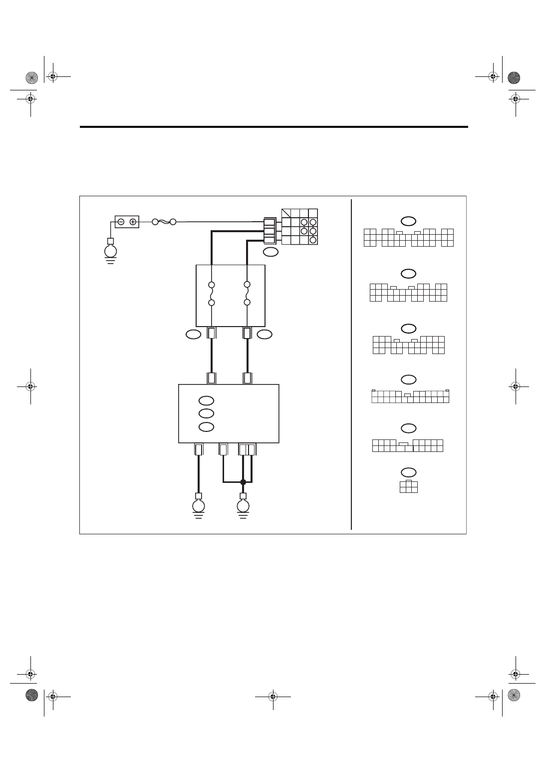
G: DTC B0104 ACC POWER FAILURE
DTC DETECTING CONDITION:
ACC power supply circuit is open or shorted.
TROUBLE SYMPTOM:
Rear wiper may not operate at ACC position.
WIRING DIAGRAM:
LAN00172
A1
A24
1
8
B72
1
B
2
4
ACC
ACC
OFF
IG
ON
B52
3 4
1 2
8 9 10 11
12 13 14 15 16 17 18 19 20 21 22 23 24
5
6 7
B280
B:
B281
C:
5 6 7
8
2
1
9
4
3
10
24
22 23
25
11 12 13 14 15
26
27 28
16 17 18 19
20 21
5
4
6 7
8
2
1
9
3
10
22
23
11 12 13 14 15
24 25
26 27
16 17 18
28 29
19 20
21
30
i84
A:
1 2
3 4
5 6
7 8
9 10 11 12 13 14 15 16 17 18 19 20 21 22 23
24 25
26 27 28 29
30 31 32 33
34 35
1 2 3 4
5 6 7 8 9
10 11 12
19 20
13 14 15 16 17 18
i5
B52
i5
E
MAIN SBF
FB-28 No.31
i84
B280
B:
A:
B281
C:
BATTERY
BODY INTEGRATED
MODULE
A
CC PO
WER SUPPL
Y
IG PO
WER SUPPL
Y
IGNITION SWITCH
A21
C9
B22
C8
E
E
FB-37 No.12
1
3
4 5 6
2
B72
FUSE & RELAY BOX

LAN(diag)-41
LAN SYSTEM (DIAGNOSTICS)
Diagnostic Procedure with Diagnostic Trouble Code (DTC)
Step
Check
Yes
No
1
CHECK FUSE.
1) Turn the ignition switch to OFF.
2) Remove the fuse (No. 31).
Is the fuse blown out?
Replace the fuse
(No. 31). If the
replaced fuse has
blown out easily,
repair the short cir-
cuit of harness
between fuse (No.
31) and body inte-
grated module.
2
CONTINUITY CHECK OF WIRING HAR-
NESS.
1) Disconnect the connector from body inte-
grated module.
2) Turn the ignition switch to ACC or ON.
3) Measure the voltage between body inte-
grated module connector and chassis ground.
Connector & terminal
(i84) No. 24 (+) — Chassis ground (
−
):
Is the voltage more than 10 V? Go to step 3.
Repair the har-
ness for open or
shorted circuit
between body inte-
grated module and
fuse.
3
CHECK POOR CONTACT IN CONNECTOR. Is there poor contact in body
integrated module connector?
Repair the poor
contact connector.
4
CHECK BODY INTEGRATED MODULE HAR-
NESS.
1) Connect all the connectors.
2) Perform the clear memory mode.
3) Read DTC.
Is DTC displayed on Subaru
Select Monitor?
Replace the body
integrated mod-
ule. <Ref. to SL-
44, Body Inte-
grated Module.>
Temporary poor
contact occurs.
LAN(diag)-42
LAN SYSTEM (DIAGNOSTICS)
Diagnostic Procedure with Diagnostic Trouble Code (DTC)
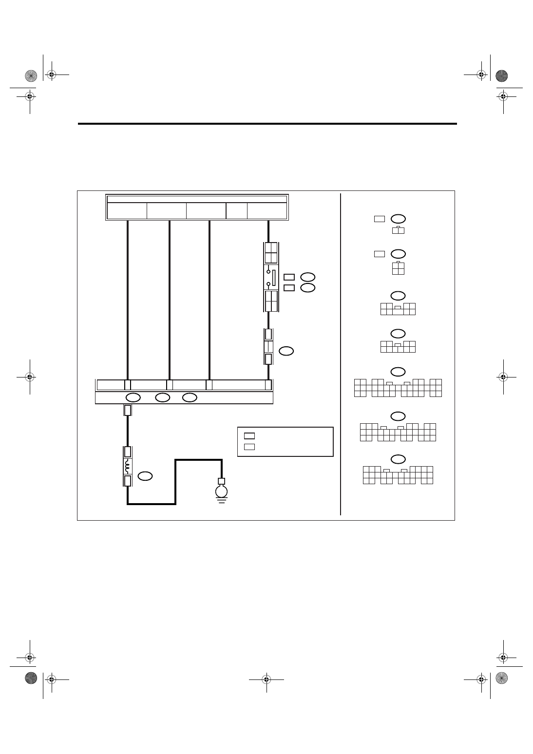
H: DTC B0106 SHIFT LOCK CIRCUIT FAILURE
DTC DETECTING CONDITION:
Shift lock circuit is ground shorted.
TROUBLE SYMPTOM:
Key interlock does not unlock or lock.
WIRING DIAGRAM:
B6
FB-28
F/B FUSE No.31
(ACC)
FB-37
F/B FUSE No.12
(IG)
MB-28
M/B FUSE No.34
(B)
FB-3
F/B FUSE No.8
(B)
E
9
5
3
4
A24
C23
C1
A1
i84
A:
B280
B:
B281
C:
B159
1 2
3 4
5 6 7 8 9 10
B116
1 2
3 4
9
5 6
7
8
B159
5 6 7
8
2
1
9
4
3
10
24
22 23
25
11 12 13 14 15
26
27 28
16 17 18 19
20 21
B281
C:
5
4
6 7
8
2
1
9
3
10
22
23
11 12 13 14 15
24 25
26 27
16 17 18
28 29
19 20
21
30
B280
B:
B116
3 4
1 2
1 2
3 4
5 6
7 8
9 10 11 12 13 14 15 16 17 18 19 20 21 22 23
24 25
26 27 28 29
30 31 32 33
34 35
A:
i84
LAN00173
1 2
B65
WC
B64
OC :
:
REF.TO POWER SUPPLY ROUTING
JOINT FUSE BOX
BODY INTEGRATED MODULE
SHIFT LOCK
SOLENOID
: WITH CRUISE CONTROL
: WITHOUT CRUISE CONTROL
WC
OC
B65
WC
B64
OC :
:
STOP LIGHT
SWITCH
23
WC
OC
12
OC
WC
Нет комментариевНе стесняйтесь поделиться с нами вашим ценным мнением.
Текст