Subaru Legacy (2005 year). Service manual — part 684
6MT-83
MANUAL TRANSMISSION AND DIFFERENTIAL
Driven Gear Assembly
20.Driven Gear Assembly
A: REMOVAL
1) Remove the manual transmission assembly
from vehicle. <Ref. to 6MT-34, REMOVAL, Manual
Transmission Assembly.>
2) Prepare the transmission for overhaul. <Ref. to
6MT-40, Preparation for Overhaul.>
3) Remove the oil pipe, neutral position switch,
back-up light switch and harness. <Ref. to 6MT-42,
REMOVAL, Oil Pipe.> <Ref. to 6MT-45, REMOV-
AL, Neutral Position Switch.> <Ref. to 6MT-43, RE-
MOVAL, Back-up Light Switch.>
4) Remove the extension case. <Ref. to 6MT-47,
REMOVAL, Extension Case.>
5) Remove the transfer driven gear. <Ref. to 6MT-
58, REMOVAL, Transfer Driven Gear.>
6) Remove the center differential. <Ref. to 6MT-60,
REMOVAL, Center Differential.>
7) Remove the oil pump. <Ref. to 6MT-61, RE-
MOVAL, Oil Pump.>
8) Remove the transmission case. <Ref. to 6MT-
64, REMOVAL, Transmission Case.>
9) Remove the driven gear assembly. <Ref. to
6MT-69, REMOVAL, Main Shaft Assembly.>
10) Remove the 1st needle bearing.
11) Remove the thrust needle bearing.
B: INSTALLATION
1) Adjust the main shaft snap ring. <Ref. to 6MT-
81, ADJUSTMENT, Main Shaft Assembly.>
2) Adjust the 1st-2nd shifter rod. <Ref. to 6MT-115,
ADJUSTMENT, Shifter Fork and Rod.>
3) Install the thrust needle bearing.
NOTE:
Be sure the thrust needle bearing is installed in
proper direction.
4) Install the 1st needle bearing.
5) Install the driven gear assembly. <Ref. to 6MT-
70, INSTALLATION, Main Shaft Assembly.>
6) Install the transmission case. <Ref. to 6MT-65,
INSTALLATION, Transmission Case.>
7) Adjust backlash at axial direction of driven gear
assembly. <Ref. to 6MT-90, ADJUSTMENT, Driv-
en Gear Assembly.>
8) Install the oil pump. <Ref. to 6MT-62, INSTAL-
LATION, Oil Pump.>
9) Install the center differential. <Ref. to 6MT-60,
INSTALLATION, Center Differential.>
10) Install the transfer driven gear. <Ref. to 6MT-
58, INSTALLATION, Transfer Driven Gear.>
11) Install the extension case. <Ref. to 6MT-47, IN-
STALLATION, Extension Case.>
12) Install the oil pipe, neutral position switch,
back-up light switch and harness. <Ref. to 6MT-42,
INSTALLATION, Oil Pipe.> <Ref. to 6MT-45, IN-
STALLATION, Neutral Position Switch.> <Ref. to
6MT-43, INSTALLATION, Back-up Light Switch.>
13) Install the manual transmission assembly into
vehicle. <Ref. to 6MT-36, INSTALLATION, Manual
Transmission Assembly.>
MT-00586
MT-00587
6MT-84
MANUAL TRANSMISSION AND DIFFERENTIAL
Driven Gear Assembly
C: DISASSEMBLY
NOTE:
Each sleeve and hub engage at specified position.
Before disassembly, put marks on the engagement
position of sleeve and hub.
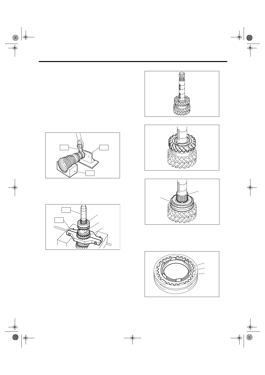
1) Secure the ST on workbench.
ST
18664AA000
BASE
2) Unlock the caulking portion of lock nut.
3) Install the ST3 to lock nut, set the driven gear as-
sembly on ST, then remove the lock nut and wash-
er.
ST1
18666AA000 HOLDER
ST2
18664AA000 BASE
ST3
18620AA000 ADAPTER WRENCH
4) Install the ST1 to 4th gear, then remove the ball
bearing, 5th-6th driven gear and 3rd-4th driven
gear.
ST1
18723AA000 REMOVER
ST2
499877000
RACE 4-5 INSTALLER
5) Remove the driven gear key.
6) Remove the 2nd gear.
7) Remove the needle bearing and 1st-2nd sleeve.
8) Remove the outer baulk ring, 2nd synchro cone
and inner baulk ring.
(A) Ball bearing
(B) 5th-6th driven gear
(C) 3rd-4th driven gear
MT-00588
ST3
ST2
ST1
MT-00589
(A)
(B)
(C)
ST2
ST1
(A) Needle bearing
(B) 1st-2nd sleeve
(A) Outer baulk ring
(B) 2nd synchro cone
(C) Inner baulk ring
MT-00590
MT-00591
(A)
(B)
MT-00592
MT-00593
(B)
(A)
(C)
6MT-85
MANUAL TRANSMISSION AND DIFFERENTIAL
Driven Gear Assembly
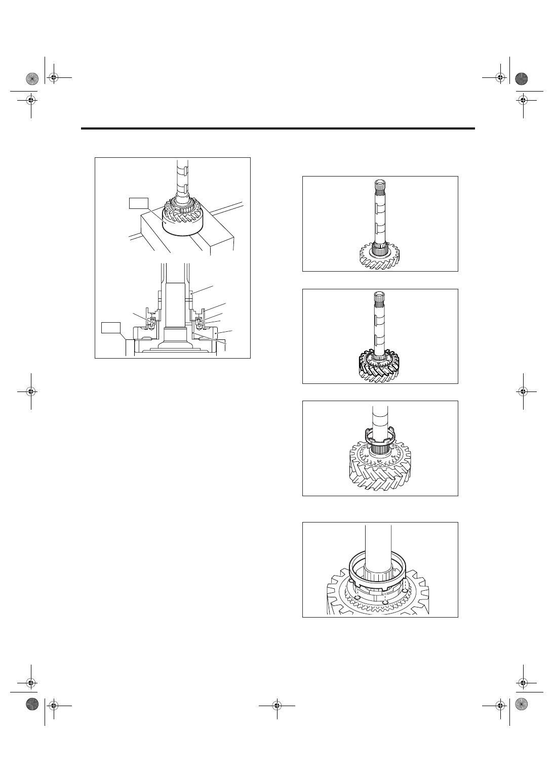
9) Using the ST, remove each parts.
ST
18754AA000
REMOVER
D: ASSEMBLY
NOTE:
When replacing the following part, replace them as
a set.
• Sleeve and hub
• Outer baulk ring, 1st synchro cone, inner baulk
ring
• Outer baulk ring, 2nd synchro cone, inner baulk
ring
1) Apply sufficient amount of gear oil to the main
shaft, 1st needle bearing and inner periphery of 1st
driven gear.
2) Install the 1st needle bearing.
3) Install the 1st driven gear to driven shaft.
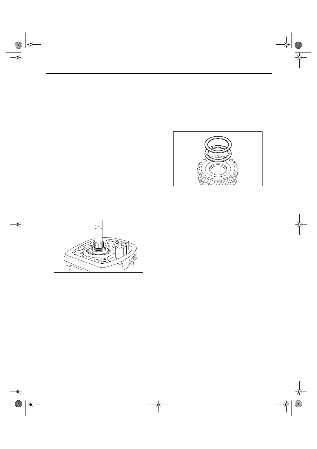
4) Install the inner baulk ring.
5) Align protrusion portions of the 1st synchro cone
to the holes of 1st drive gear to install.
(A) 2nd bushing
(B) 1st-2nd hub
(C) Outer baulk ring
(D) 1st synchro cone
(E) Inner baulk ring
(F) 1st driven gear
(G) 1st needle bearing
(A)
(E)
(B)
(C)
(D)
(F)
(G)
MT-00594
ST
ST
MT-00595
MT-00596
MT-00597
MT-00598
6MT-86
MANUAL TRANSMISSION AND DIFFERENTIAL
Driven Gear Assembly
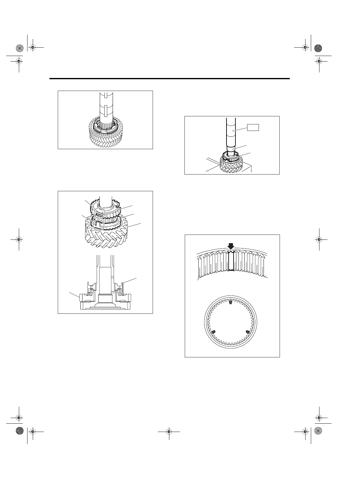
6) Install the outer baulk ring.
7) Install the 1st-2nd hub.
NOTE:
• Align the protrusion portion of outer baulk ring
and cutout portion of 1st-2nd hub, then install.
• Be sure the 1st-2nd hub is installed in proper di-
rection.
8) Using the ST, install the 2nd hub.
ST
18654AA000
INSTALLER
CAUTION:
Do not apply pressure in excess of 40 kN (4.0
ton, 4.4 US ton, 3.9 Imp ton).
9) Make sure the 1st drive gear is smoothly turned
by hand. If it is not rotated smoothly, reassemble it.
10) Install the shifting insert key in proper place of
1st-2nd sleeve.
NOTE:
Angle of each shifting insert key is 120
°.
(A) 1st-2nd hub
(B) Outer baulk ring
(C) Cutout portion of 1st-2nd hub
(D) Protrusion of outer baulk ring
(E) 1st driven gear
MT-00599
MT-00600
(E)
(D)
(C)
(A)
(B)
(E)
(A)
(A) 2nd bushing
(B) 1st-2nd hub
MT-00601
(B)
(A)
ST
MT-00602
Нет комментариевНе стесняйтесь поделиться с нами вашим ценным мнением.
Текст