Subaru Legacy (2005 year). Service manual — part 682
6MT-75
MANUAL TRANSMISSION AND DIFFERENTIAL
Main Shaft Assembly
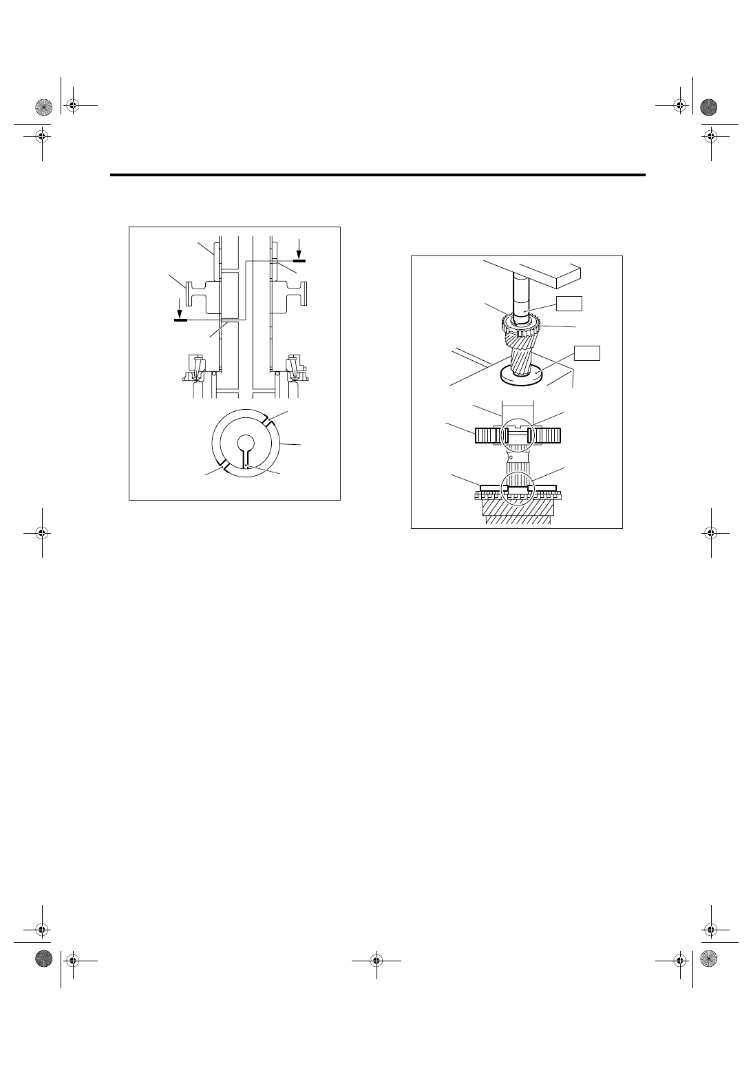
(2) Install to the main shaft, taking care not to
overlap the main shaft oil hole and 4th bushing
oil hole.
(3) Using the ST, press into 3rd-4th hub and 4th
bushing at a time.
ST1
18651AA000 INSTALLER
ST2
398177700
INSTALLER
CAUTION:
Do not apply pressure in excess of 40 kN (4.0
ton, 4.4 US ton, 3.9 Imp ton).
NOTE:
When pressing into 3rd-4th hub and 4th bushing,
move the outer baulk ring and align the protrusion
of outer baulk ring to cutout portion of 3rd-4th bush-
ing.
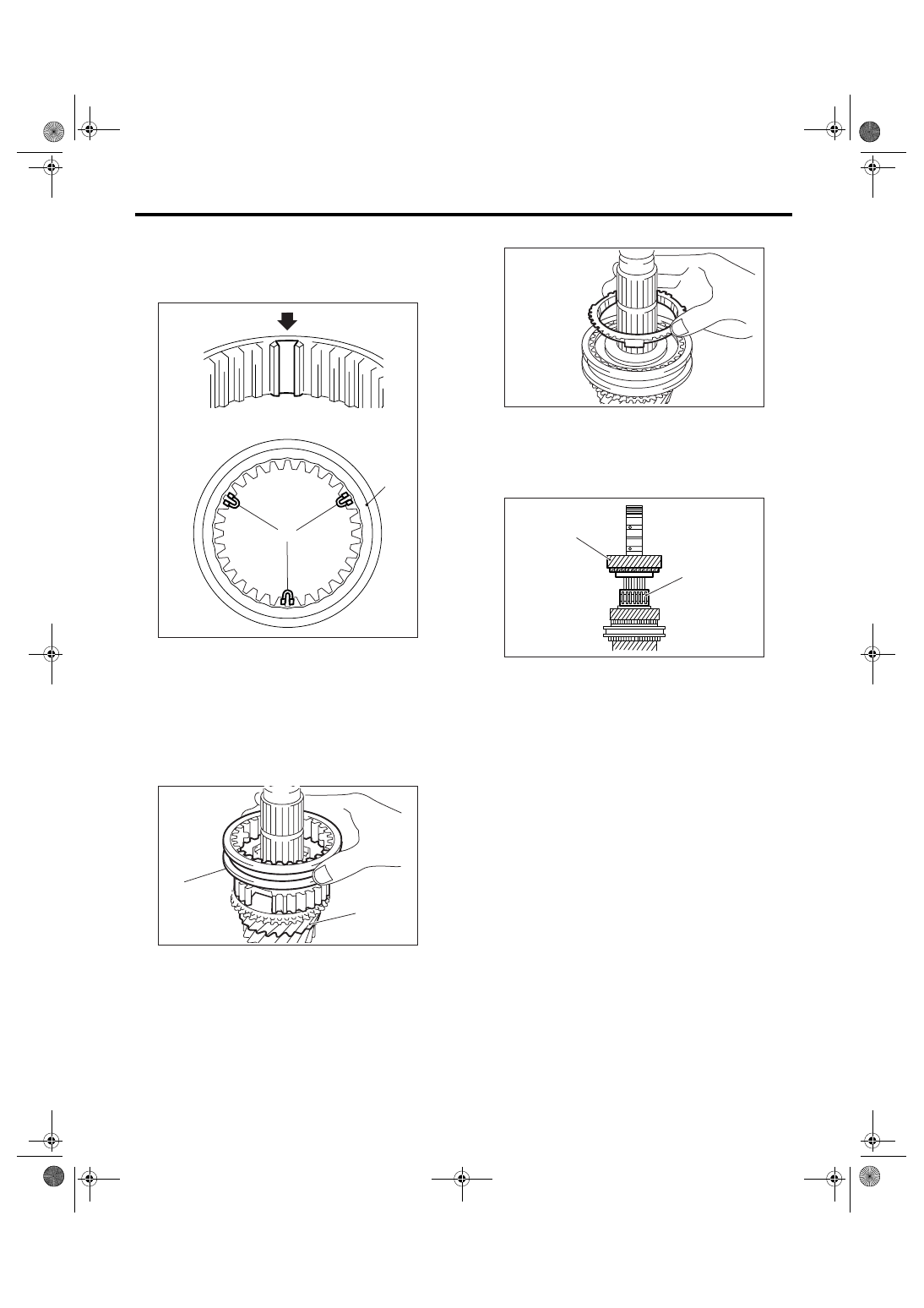
5) Be sure 3rd drive gear is rotated smoothly by
hands. If it is not rotated smoothly, reassemble it.
(A) 4th bushing
(B) 3rd-4th hub
(C) 4th bushing oil hole
(D) Main shaft oil hole
MT-00885
(A)
(B)
A
(D)
(C)
A
(C)
(C)
(D)
A - A
(A)
(A) 3rd-4th hub
(B) Outer baulk ring
(C) Cutout portion of 3rd-4th hub
(D) Protrusion of outer baulk ring
(E) 4th bushing
MT-00555
(D)
(C)
(A)
(E)
(E)
(A)
(B)
ST1
ST2
6MT-76
MANUAL TRANSMISSION AND DIFFERENTIAL
Main Shaft Assembly
6) Install the 3rd-4th shifting insert key to proper
position of 3rd-4th sleeve.
NOTE:
Angle of each shifting insert key is 120
°.
7) Install the 3rd-4th sleeve to 3rd-4th hub.
NOTE:
• 3rd-4th sleeve has an identification groove.
• Install the 3rd-4th sleeve with the groove facing
towards 3rd drive gear side.
8) Install the 4th baulk ring.
9) Apply sufficient amount of gear oil to the main
shaft, and the inside of 4th needle bearing and 4th
drive gear.
10) Install the 4th needle bearing and 4th drive
gear.
(A) 3rd-4th sleeve
(B) 3rd-4th shifting insert key
(A) 3rd drive gear
(B) 3rd-4th sleeve identification groove (one line)
MT-00673
(B)
(A)
MT-00563
(A)
(B)
(A) 4th needle bearing
(B) 4th drive gear
MT-00564
(A)
(B)
MT-00565
6MT-77
MANUAL TRANSMISSION AND DIFFERENTIAL
Main Shaft Assembly
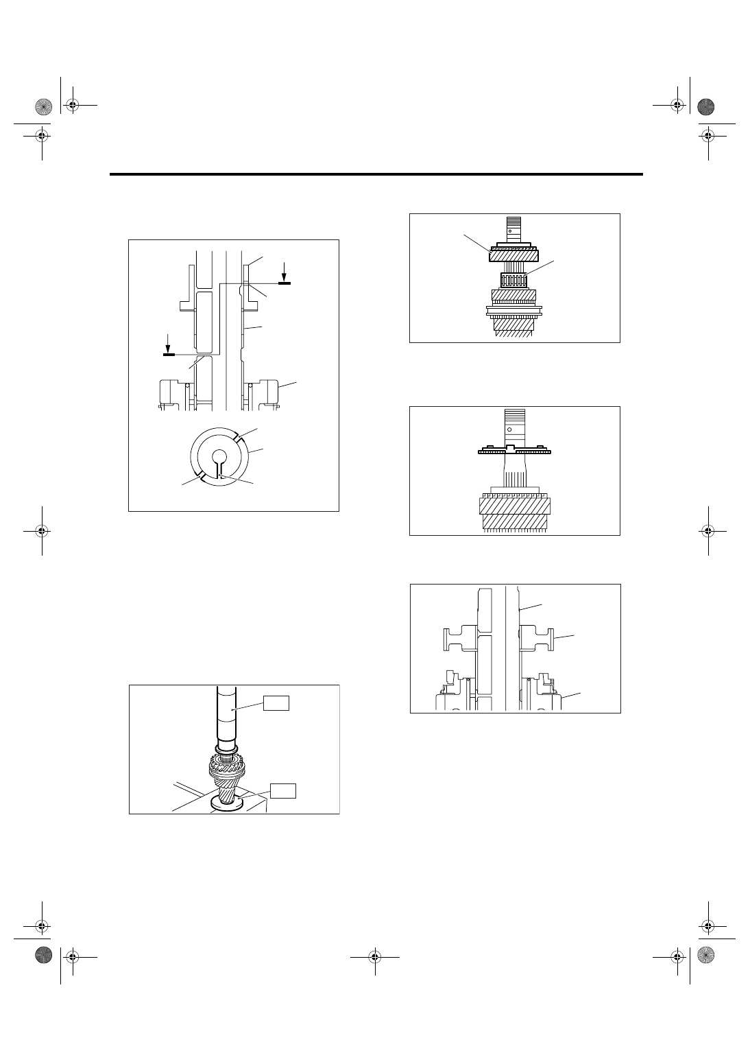
11) Install the 5th bushing.
(1) Install to the main shaft, taking care not to
overlap the main shaft oil hole and 5th bushing
oil hole.
(2) Using the ST, press into 5th bushing.
ST1
18651AA000 INSTALLER
ST2
398177700 INSTALLER
CAUTION:
Do not apply pressure in excess of 40 kN (4.0
ton, 4.4 US ton, 3.9 Imp ton).
12) Be sure 4th drive gear is rotated smoothly by
hands. If it is not rotated smoothly, reassemble it.
13) Apply sufficient amount of gear oil to the main
shaft, and the inside of 5th needle bearing and 5th
drive gear.
14) Install the 5th needle bearing and 5th drive
gear.
15) Install the 5th baulk ring.
16) Install the 5th-6th hub.
(1) Set the 5th-6th hub to main shaft paying at-
tention to the installing direction.
(A) 5th bushing
(B) Main shaft oil hole
(C) Main shaft
(D) 5th bushing oil hole
(E) 4th drive gear
MT-00566
(C)
(A)
A - A
(C)
(B)
(A)
A
(D)
(C)
(E)
(B)
A
MT-00567
ST1
ST2
(A) 5th needle bearing
(B) 5th drive gear
(A) Main shaft
(B) 5th-6th hub
(C) 5th drive gear
(A)
(B)
MT-00568
MT-00569
MT-00570
(A)
(B)
(C)
6MT-78
MANUAL TRANSMISSION AND DIFFERENTIAL
Main Shaft Assembly
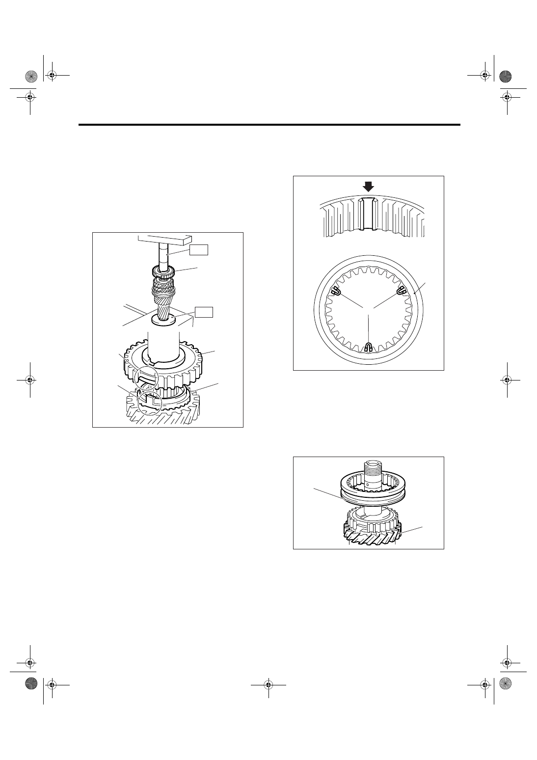
(2) Using the ST, press into 5th-6th hub.
ST1
18651AA000 INSTALLER
ST2
398177700
INSTALLER
CAUTION:
Do not apply pressure in excess of 40 kN (4.0
ton, 4.4 US ton, 3.9 Imp ton).
NOTE:
When pressing into 5th-6th hub, move the outer
baulk ring and align the protrusion of outer baulk
ring to cutout portion of 5th-6th bushing.
17) Be sure 5th drive gear is rotated smoothly by
hands. If it is not rotated smoothly, reassemble it.
18) Install the 5th-6th shifting insert key to proper
position of 5th-6th sleeve.
NOTE:
Angle of each shifting insert key is 120
°.
19) Install the 5th-6th sleeve to 5th-6th hub.
NOTE:
• 5th-6th sleeve has two identification grooves.
• Install the 5th-6th sleeve with the groove facing
towards 5th drive gear side.
(A) 5th-6th hub
(B) Outer baulk ring
(C) Cutout portion of 5th-6th hub
(D) Protrusion of outer baulk ring
MT-00571
(D)
(C)
(B)
(A)
(A)
ST1
ST2
(A) 5th-6th sleeve
(B) Shifting insert key
(A) 5th drive gear
(B) 5th-6th sleeve identification grooves (two lines)
MT-00673
(B)
(A)
MT-00572
(A)
(B)
Нет комментариевНе стесняйтесь поделиться с нами вашим ценным мнением.
Текст