Subaru Legacy (2005 year). Service manual — part 685
6MT-87
MANUAL TRANSMISSION AND DIFFERENTIAL
Driven Gear Assembly
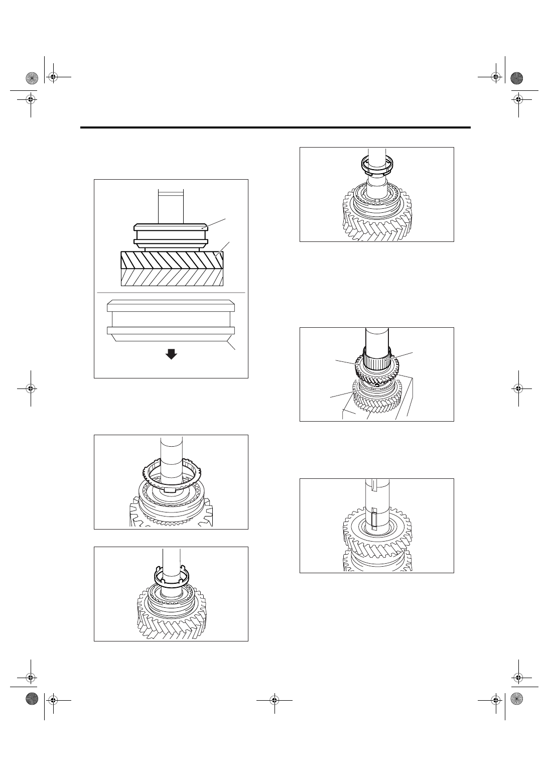
11) Install the 1st-2nd sleeve to 1st-2nd hub.
NOTE:
Be sure the 1st-2nd sleeve is installed in proper di-
rection.
12) Install the outer baulk ring.
13) Install the 2nd synchro cone.
14) Install the inner baulk ring.
15) Apply sufficient amount of gear oil to the bush-
ing, 2nd needle bearing and inner periphery of 2nd
drive gear.
16) Install the 2nd needle bearing and 2nd driven
gear.
NOTE:
Align the protrusion portion of 2nd synchro cone
with 2nd driven gear hole, then install.
17) Install the key.
(A) 1st driven gear
(B) 1st-2nd sleeve
(C) 1st driven gear side
MT-00603
(B)
(A)
(C)
(B)
MT-00604
MT-00605
(A) 2nd needle bearing
(B) 2nd driven gear
(C) Protrusion portion of 2nd synchro cone
MT-00606
(A)
(C)
(B)
MT-00607
MT-00608
6MT-88
MANUAL TRANSMISSION AND DIFFERENTIAL
Driven Gear Assembly
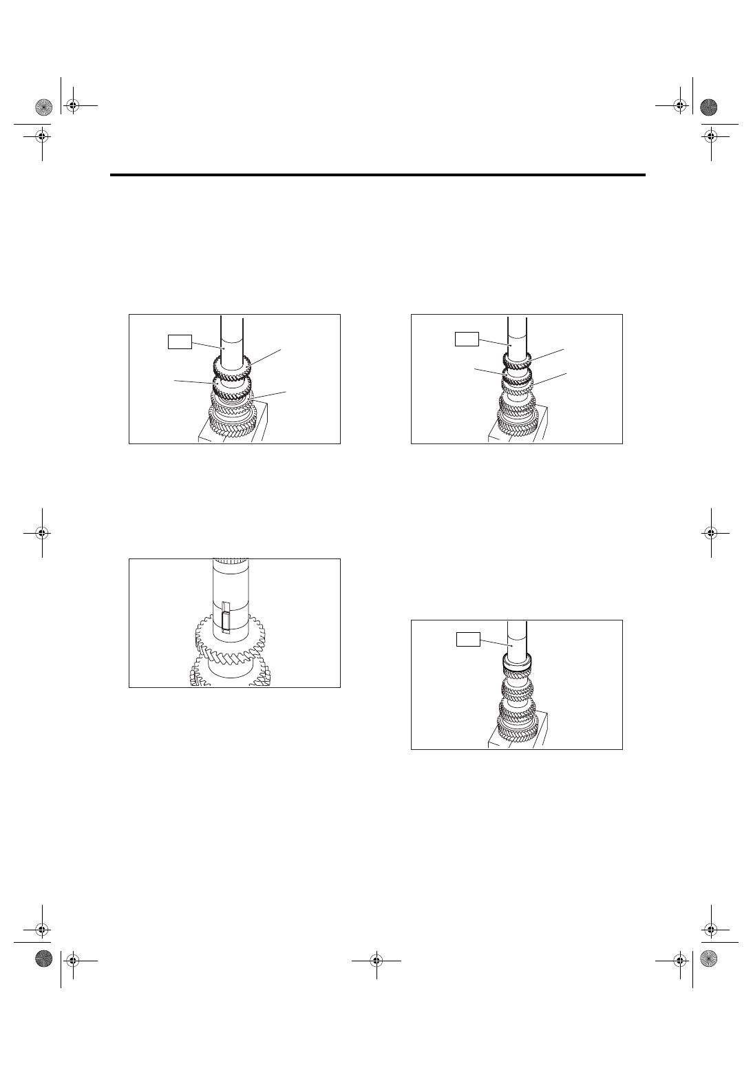
18) Using the ST, install the 3rd-4th driven gear.
ST
18654AA000
INSTALLER
CAUTION:
Do not apply pressure in excess of 40 kN (4.0
ton, 4.4 US ton, 3.9 Imp ton).
NOTE:
• Be sure the 3rd-4th driven gear is installed in
proper direction.
• Align the groove of 3rd-4th driven gear with key.
19) Make sure the 2nd driven gear is smoothly
turned by hand. If it is not rotated smoothly, reas-
semble it.
20) Install the key.
21) Using the ST, install the 5th-6th driven gear.
ST
18654AA000
INSTALLER
CAUTION:
Do not apply pressure in excess of 40 kN (4.0
ton, 4.4 US ton, 3.9 Imp ton).
NOTE:
• Be sure the 5th-6th driven gear is installed in
proper direction.
• Align the groove of 5th-6th driven gear with key.
22) Using the ST, install the ball bearing.
ST
18654AA000
INSTALLER
CAUTION:
Do not apply pressure in excess of 40 kN (4.0
ton, 4.4 US ton, 3.9 Imp ton).
NOTE:
Be sure the ball bearing is installed in proper direc-
tion.
23) Make sure the ball bearing is smoothly turned
by hand. If it is not rotated smoothly, reassemble it.
24) Install a new lock nut.
(A) 4th gear
(B) 3rd gear
(C) 2nd gear
(A)
(C)
(B)
ST
MT-00609
MT-00610
(A) 6th gear
(B) 5th gear
(C) 4th gear
(B)
ST
(A)
(C)
MT-00611
ST
MT-00612
6MT-89
MANUAL TRANSMISSION AND DIFFERENTIAL
Driven Gear Assembly
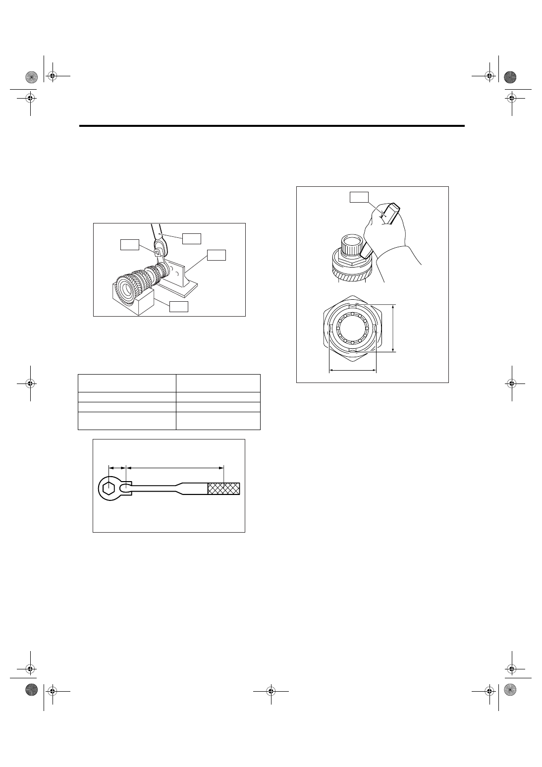
25) Install the ST3 to lock nut, then install the ST1
and ST2 to the driven gear assembly and tighten
the lock nut.
ST1
18666AA000 HOLDER
ST2
18664AA000 BASE
ST3
18620AA000 ADAPTER WRENCH
ST4
18852AA000 TORQUE WRENCH
Tightening torque:
530 N
⋅
m (54.0 kgf-m, 391 ft-lb)
NOTE:
If torque wrench except ST4 is used, calculate the
following calculation formula, then tighten the lock
nut.
T = L1 / (0.1 + L1)
× 570
26) Using the ST, caulk the lock nut at four points at
dimension A of 44
±0.5 mm (1.73±0.02 in).
ST
18669AA000
PUNCH
NOTE:
Do not damage the caulking portion of lock nut.
T
N
⋅m (kgf-m, ft-lb) Setting value of torque
wrench
L1
m (in) Torque wrench length
0.1 m (3.94 in)
ST length
570 N
⋅m (58.1 kgf-m, 420 ft-lb) Tightening torque of lock
nut:
(A) 0.1 m (3.94 in)
MT-00613
ST1
ST2
ST4
ST3
(A)
L1
MT-00614
MT-00615
A
A
ST
6MT-90
MANUAL TRANSMISSION AND DIFFERENTIAL
Driven Gear Assembly
E: INSPECTION
Disassembled parts should be washed with un-
leaded gasoline first and then inspected carefully.
1) Bearing
Replace the bearings in the following cases.
• When there are wear, rust and damage on the
bearing.
• When bearing that fails to turn smoothly or
makes noise when turned.
• When bearings have other defects.
2) Bushing (each gear)
Replace the bushing in following cases.
• When the sliding surface is damaged or abnor-
mally worn.
3) Gear
Replace the gear in the following cases.
• When the gear teeth surfaces are broken or ex-
cessively worn.
• When the parts that contact the baulk ring is
damaged.
• When the inner surface of gear is damaged.
4) Baulk ring, synchro cone
Replace the baulk ring and synchro cone in the fol-
lowing case.
• When there are wear, rust and damage on the
baulk ring.
5) Shifting insert key
Replace the shifting insert key if deformed, exces-
sively worn or defective in any way.
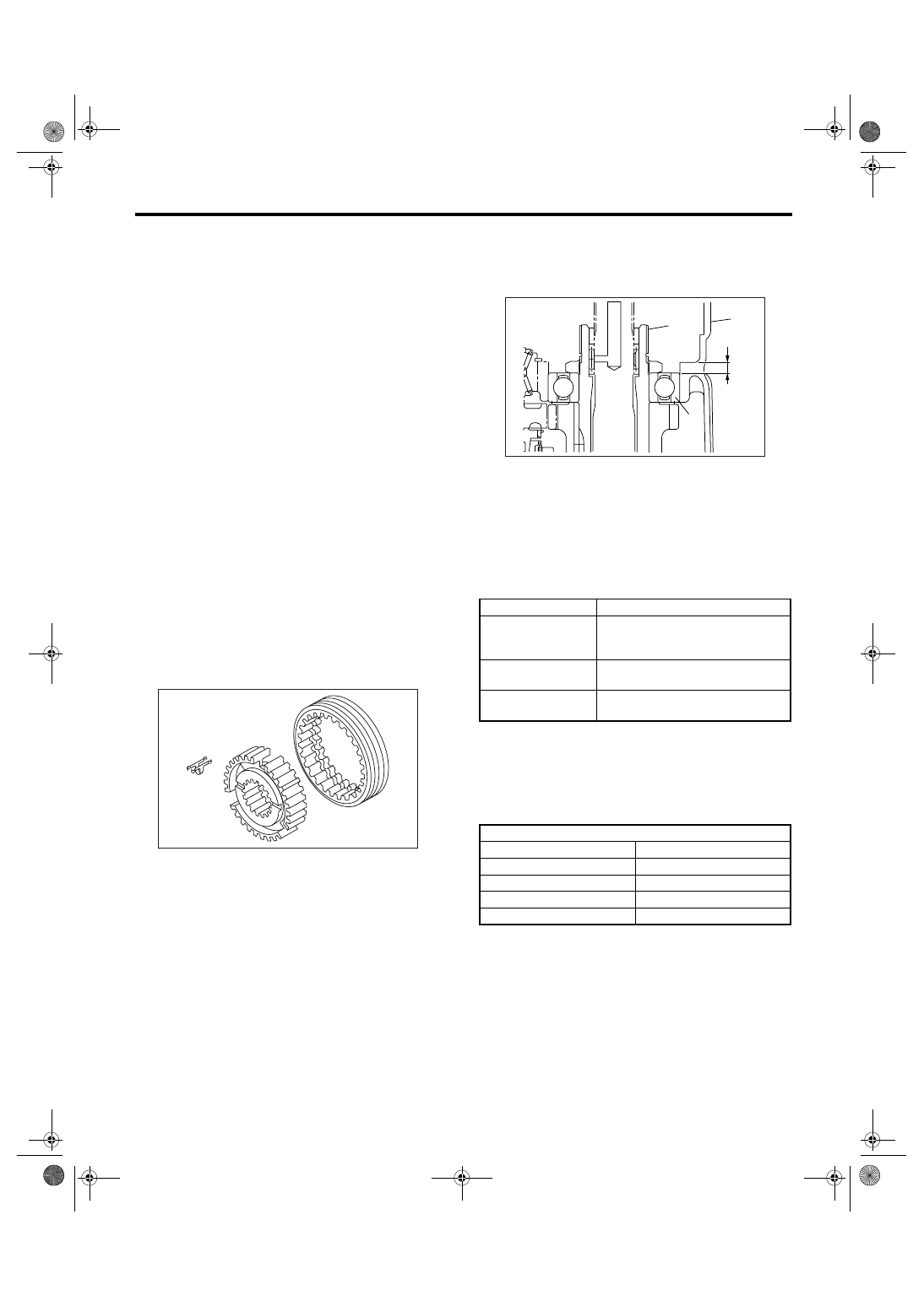
F: ADJUSTMENT
1) Measure length “H”, which is from transmission
case and oil pump cover mating surface to ball
bearing edge.
2) Using the following calculation formula, calcu-
late the washer thickness of driven gear assembly.
T = H
− {5.8±0.05 mm (0.23±0.002 in)} − {0.1 — 0.3
mm (0.0039 — 0.0118 in)}
3) Select 0 to 3 washers from the following table to
adjust backlash closest to specification.
Backlash specification at axial direction of driv-
en gear assembly:
0.1 — 0.3 mm (0.0039 — 0.0118 in)
MT-00581
(A) Transmission case
(B) Ball bearing
(C) Driven gear ASSY
t
Thickness of washer
H
Length from transmission case and
oil pump cover mating surface to ball
bearing edge
5.8
±0.05 mm
(0.23
±0.002 in)
Thickness of collar
0.1 to 0.3 mm
(0.0039 to 0.0118 in)
Backlash specification at axial direc-
tion of driven gear assembly
Washer
Part No.
Thickness t mm (in)
803072030
0.15 (0.0059)
803072031
0.30 (0.0118)
803072032
0.45 (0.0177)
803072033
0.60 (0.0236)
MT-00616
(A)
H
(C)
(B)
Нет комментариевНе стесняйтесь поделиться с нами вашим ценным мнением.
Текст