Subaru Legacy (2005 year). Service manual — part 683
6MT-79
MANUAL TRANSMISSION AND DIFFERENTIAL
Main Shaft Assembly
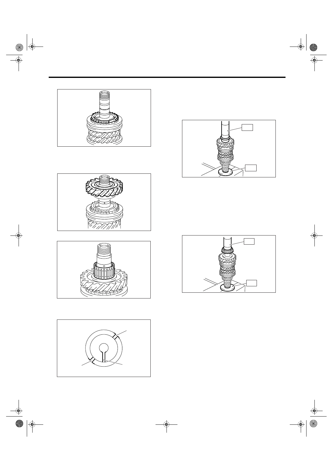
20) Install the 6th baulk ring.
21) Apply sufficient amount of gear oil to the main
shaft, and the inside of 6th needle bearing and 6th
drive gear.
22) Install the 6th drive gear.
23) Install the 6th needle bearing.
24) Set the 6th bushing to main shaft, taking care
not to overlap the 6th bushing oil hole and main
shaft oil hole.
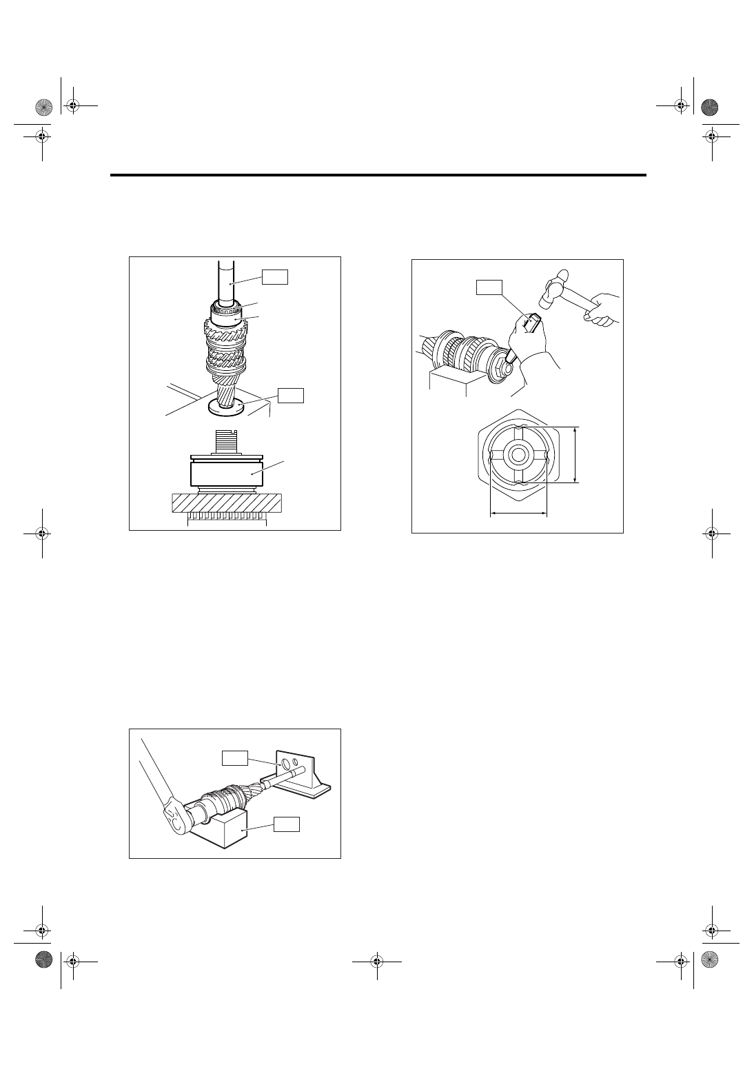
25) Using the ST, install the 6th bushing.
ST1
18651AA000 INSTALLER
ST2
398177700 INSTALLER
CAUTION:
Do not apply pressure in excess of 40 kN (4.0
ton, 4.4 US ton, 3.9 Imp ton).
26) Be sure 6th drive gear is rotated smoothly by
hands. If it is not rotated smoothly, reassemble it.
27) Using the ST, install the inner race of inner
bearing.
ST1
18651AA000 INSTALLER
ST2
398177700 INSTALLER
CAUTION:
Do not apply pressure in excess of 40 kN (4.0
ton, 4.4 US ton, 3.9 Imp ton).
28) Using the ST, install the retainer and inner race
of outer bearing.
ST1
18651AA000 INSTALLER
ST2
398177700 INSTALLER
CAUTION:
Do not apply pressure in excess of 40 kN (4.0
ton, 4.4 US ton, 3.9 Imp ton).
(A) 6th bushing oil hole
(B) Main shaft oil hole
MT-00573
MT-00574
MT-00575
(A)
(A)
(B)
MT-00576
MT-00577
ST1
ST2
ST1
ST2
MT-00578
6MT-80
MANUAL TRANSMISSION AND DIFFERENTIAL
Main Shaft Assembly
NOTE:
• Be sure the retainer is installed in proper direc-
tion.
• Press until the retainer has no backlash or the
bearing can be rotated smoothly by hands.
29) Be sure the taper roller bearing is rotated
smoothly by hands. If it is not rotated smoothly, re-
place the taper roller bearing as a set and reassem-
ble them.
30) Install the lock washer and new lock nut.
31) Set the main shaft assembly to ST and tighten
the lock nut.
ST1
18665AA000 HOLDER
ST2
18664AA000 BASE
Tightening torque:
392 N
⋅
m (40 kgf-m, 289.1 ft-lb)
32) Using the ST, caulk the lock nut at four points at
dimension A of 27
±0.3 mm (1.06±0.01 in).
ST
18668AA000
PUNCH
NOTE:
Do not damage the caulking portion of lock nut.
E: INSPECTION
Disassembled parts should be washed with un-
leaded gasoline first and then inspected carefully.
1) Bearing
Replace the bearings in the following cases.
• When there are wear, rust and damage on the
bearing.
• When bearing that fails to turn smoothly or
makes noise while turning.
• When bearings have other defects.
2) Bushing (each gear)
Replace the bushing in following cases.
• When the sliding surface is damaged or abnor-
mally worn.
3) Gear
Replace the gear in the following cases.
• When the gear teeth surfaces are broken or ex-
cessively worn.
• When the parts that contact the baulk ring is
damaged.
• When the inner surface of gear is damaged.
4) Baulk ring, synchro cone
Replace the baulk ring and synchro cone in the fol-
lowing case.
• When there are wear, rust and damage on baulk
ring.
(A) Retainer
(B) Inner race of outer bearing
MT-00579
(B)
(A)
(A)
ST2
ST1
MT-00556
ST2
ST1
MT-00580
A
A
ST
6MT-81
MANUAL TRANSMISSION AND DIFFERENTIAL
Main Shaft Assembly
5) Shifting insert key
Replace the shifting insert key if deformed, exces-
sively worn or defective in any way.
F: ADJUSTMENT
1. SELECTION OF MAIN SHAFT SNAP
RING AND WASHER
NOTE:
Perform adjustment with following procedures be-
low in the following cases.
• When replacing the driven gear from 1st to 6th.
• When replacing the 1st and 2nd synchro ring as-
sembly.
• When replacing the ball bearing.
• When replacing the adapter plate.
• When replacing the driven shaft.
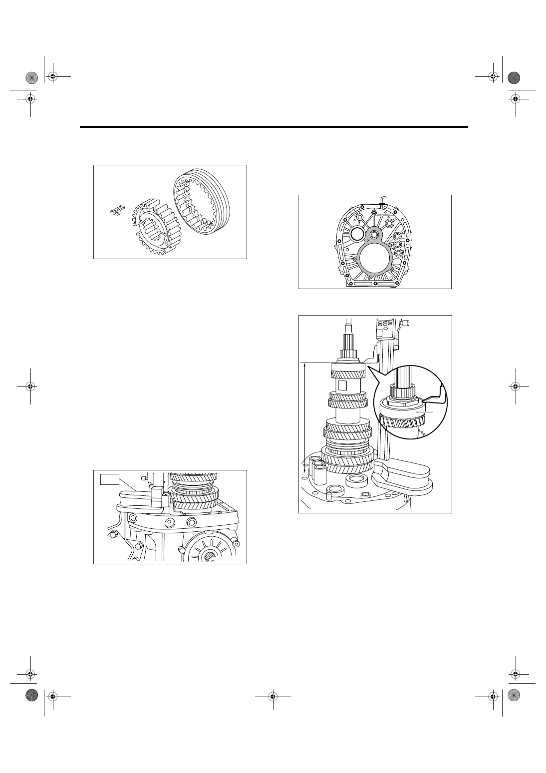
1) Insert the drive pinion assembly in adapter plate.
NOTE:
Make sure the thrust bearing outer race is not re-
moved and drive pinion is not lifted-up.
2) Set the height gauge to adapter plate. Lower the
indicator of height gauge to mating surface of
adapter plate and case, then set to zero point.
ST
18853AA000
HEIGHT GAUGE
NOTE:
• Remove the remaining gasket on edge surface
with scraper, since the adapter plate is base point
of measurement.
• Do not place the height gauge on shaded area in
the figure during the measurement.
3) Measure the height to edge surface of ball bear-
ing (height H).
MT-00581
MT-00582
ST
(A) Ball bearing
MT-00583
(A)
MT-00955
H
6MT-82
MANUAL TRANSMISSION AND DIFFERENTIAL
Main Shaft Assembly
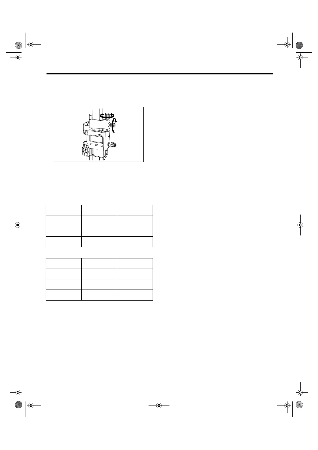
NOTE:
Set the indicator of height gauge near measuring
object, then lock the dial (1) as shown in the figure.
Turn dial (2) to set the indicator to edge surface of
bearing.
Measure five points of the ball bearing turning ev-
ery approx. 120
°. Round off each two upper and
lower measurement value. Use the remaining mid-
dle value as measurement value.
4) According to measurement value, select the
snap ring and washer from the following table.
• Snap ring
• Washer
H: mm (in)
Part No.
Thickness:
mm (in)
270.83 — 271.40
(10.66 — 10.69)
805072010
1.65 (0.065)
271.41 — 271.98
(10.69 — 10.71)
805072011
1.95 (0.077)
271.99 — 272.56
(10.71 — 10.73)
805072012
2.25 (0.089)
H: mm (in)
Part No.
Thickness:
mm (in)
270.83 — 271.40
(10.66 — 10.69)
803067012
1.6 (0.063)
271.41 — 271.98
(10.69 — 10.71)
803067011
1.3 (0.051)
271.99 — 272.56
(10.71 — .73)
803067010
1.0 (0.039)
(2)
(1)
MT-00585
Нет комментариевНе стесняйтесь поделиться с нами вашим ценным мнением.
Текст