Subaru Legacy (2005 year). Service manual — part 111
EN(H4SO 2.0)(diag)-33
ENGINE (DIAGNOSTICS)
Inspection Mode
1. PREPARATION FOR THE INSPECTION
MODE
1) Check that the battery voltage is more than 12 V
and fuel remains half [20 — 40
2 (5.3 — 10.6 US
gal, 4.4 — 8.8 Imp gal)].
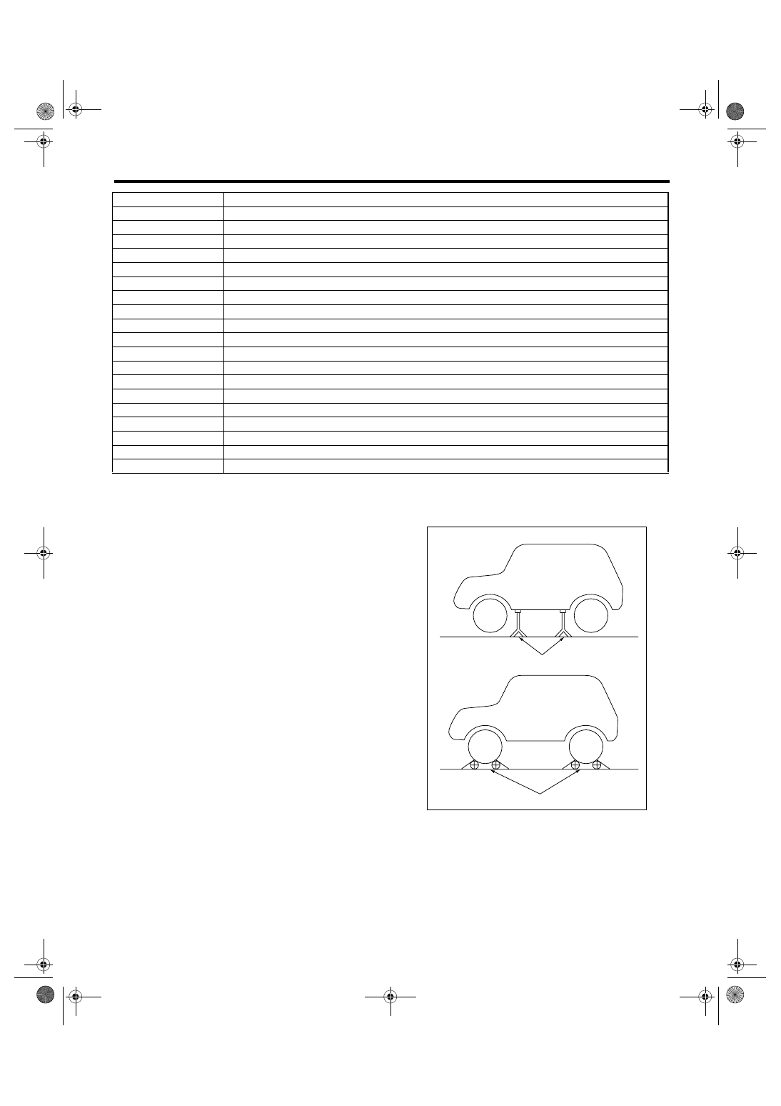
2) Lift-up the vehicle using a garage jack and place
it on rigid racks, or drive the vehicle onto free roll-
ers.
WARNING:
• Before lifting-up the vehicle, ensure parking
brakes are applied.
• Do not use a pantograph jack in place of a rig-
id rack.
• Secure a rope or wire to the front or rear tow-
ing hooks to prevent the lateral runout of front
wheels.
• Do not abruptly depress/release clutch pedal
or accelerator pedal during works even when
the engine is operating at low speeds since this
may cause vehicle to jump off free rollers.
• In order to prevent the vehicle from slipping
due to vibration, do not place any wooden
blocks or similar items between the rigid racks
and vehicle.
• Since the rear wheels will also rotate, do not
place anything near them. Also, make sure that
nobody goes in front of the vehicle.
P1571
Reference Code Incompatibility
P1572
IMM Circuit Failure (Except Antenna Circuit)
P1574
Key Communication Failure
P1576
EGI Control Module EEPROM
P1577
IMM Control Module EEPROM
P1578
Meter Failure
P2100
Throttle Actuator Control Motor Circuit/Open
P2101
Throttle Actuator Control Motor Circuit Range/Performance
P2102
Throttle Actuator Control Motor Circuit Low
P2103
Throttle Actuator Control Motor Circuit High
P2109
Throttle/Pedal Position Sensor “A” Minimum Stop Performance
P2111
Throttle Actuator Control System - Stuck Open
P2122
Throttle/Pedal Position Sensor/Switch “D” Circuit Low Input
P2123
Throttle/Pedal Position Sensor/Switch “D” Circuit High Input
P2127
Throttle/Pedal Position Sensor/Switch “E” Circuit Low Input
P2128
Throttle/Pedal Position Sensor/Switch “E” Circuit High Input
P2135
Throttle/Pedal Position Sensor/Switch “A”/”B” Voltage Correlation
P2138
Throttle/Pedal Position Sensor/Switch “D”/”E” Voltage Correlation
P2503
Charging System Voltage Low
DTC
Item
(A) Rigid racks
(B) Free rollers
EN-00041
(A)
(B)
EN(H4SO 2.0)(diag)-34
ENGINE (DIAGNOSTICS)
Inspection Mode
2. SUBARU SELECT MONITOR
1) After clearing the memory, check for any remain-
ing unresolved trouble data. <Ref. to EN(H4SO
2.0)(diag)-38, Clear Memory Mode.>
2) Idle the engine.
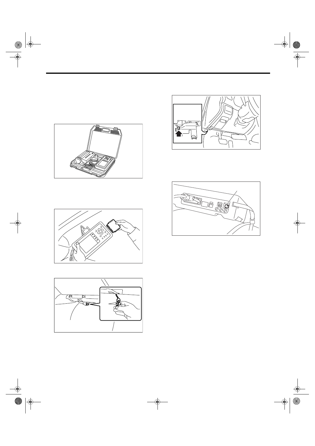
3) Prepare the Subaru Select Monitor kit. <Ref. to
EN(H4SO 2.0)(diag)-7, PREPARATION TOOL,
General Description.>
4) Connect the diagnosis cable to Subaru Select
Monitor.
5) Insert the cartridge to Subaru Select Monitor.
<Ref. to EN(H4SO 2.0)(diag)-7, PREPARATION
TOOL, General Description.>
6) Connect the test mode connector (A) located at
the lower portion of glove box.
7) Connect the Subaru Select Monitor to data link
connector located in the lower portion of the instru-
ment panel (on the driver’s side).
CAUTION:
Do not connect any scan tools except Subaru
Select Monitor or general scan tool.
8) Turn the ignition switch to ON (engine OFF), and
the Subaru Select Monitor power switch to ON.
9) On the «Main Menu» display screen, select the
{Each System Check} and press the [YES] key.
10) On the «System Selection Menu» display
screen, select the {Engine} and press the [YES]
key.
11) Press the [YES] key after the information of en-
gine type has been displayed.
12) On the «Engine Diagnosis» screen, select the
{D Check} and press the [YES] key.
13) When the “Perform D Check?” is shown on the
screen, press the [YES] key.
14) Perform subsequent procedures as instructed
on the display screen.
• If trouble still remains in the memory, the corre-
sponding DTC appears on the display screen.
NOTE:
• For detailed operation procedure, refer to the
SUBARU SELECT MONITOR OPERATION MAN-
UAL.
• For details concerning DTC, refer to “List of Diag-
nostic Trouble Code (DTC)”.
<Ref. to EN(H4SO 2.0)(diag)-64, List of Diagnostic
Trouble Code (DTC).>
EN-00038
EN-00039
PI-00201
(A)
(A) Power switch
EN-02533
(A)
EN-00040
EN(H4SO 2.0)(diag)-35
ENGINE (DIAGNOSTICS)
Inspection Mode
• Release the parking brake.
• The speed difference between front and rear
wheels may light the ABS warning light, but this in-
dicates no malfunctions. When engine control diag-
nosis is finished, perform the ABS memory
clearance procedure of self-diagnosis function.
3. GENERAL SCAN TOOL
1) After clearing the memory, check for any remain-
ing unresolved trouble data. <Ref. to EN(H4SO
2.0)(diag)-38, Clear Memory Mode.>
2) Idle the engine.
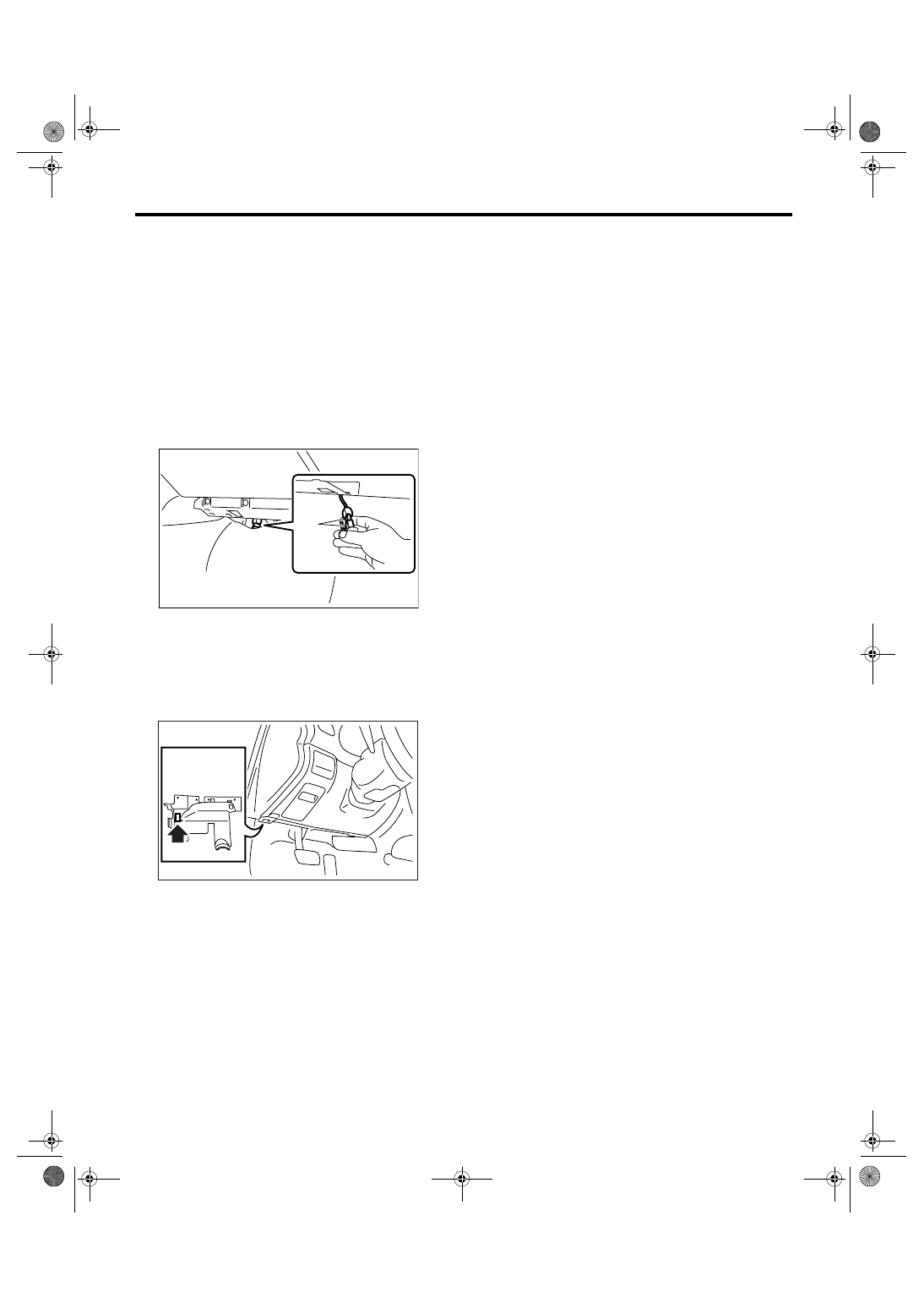
3) Connect the test mode connector (A) in the low-
er portion of glove box.
4) Connect the general scan tool to data link con-
nector located in the lower portion of the lower pan-
el of instrument panel (on the driver’s side).
CAUTION:
Do not connect any scan tools except Subaru
Select Monitor or general scan tool.
5) Start the engine.
NOTE:
• Ensure the select lever is placed in “P” position
before starting. (AT model)
• Depress the clutch pedal when starting engine.
(MT model)
6) Using the select lever or shift lever, turn the “P”
position switch and “N” position switch to ON.
7) Depress the brake pedal to turn brake switch
ON. (AT model)
8) Keep the engine speed in 2,500 — 3,000 rpm
range for 40 seconds.
9) Place the select lever or shift lever in “D” position
(AT model) or “1st” gear (MT model) and drive the
vehicle at 5 to 10 km/h (3 to 6 MPH).
NOTE:
• For AWD model, release the parking brake.
• The speed difference between front and rear
wheels may light the ABS warning light, but this in-
dicates no malfunctions. When the engine control
diagnosis is finished, perform the ABS memory
clearance procedure of self-diagnosis system.
10) Using the general scan tool, check DTC and
record the result(s).
NOTE:
• For detailed operation procedure, refer to the
general scan tool operation manual.
• For details concerning DTC, refer to “List of Diag-
nostic Trouble Code (DTC)”.
<Ref. to EN(H4SO 2.0)(diag)-64, List of Diagnostic
Trouble Code (DTC).>
PI-00201
(A)
EN-02533

EN(H4SO 2.0)(diag)-36
ENGINE (DIAGNOSTICS)
Drive Cycle
12.Drive Cycle
A: PROCEDURE
There are two drive patterns for the trouble diagno-
sis. Driving in the specified pattern allows to diag-
nose malfunctioning items listed below. After the
malfunctioning items listed below are repaired, al-
ways check whether they correctly resume their
functions by driving in the required drive pattern.
1. PREPARATION FOR DRIVE CYCLE
1) Check that the battery voltage is more than 12 V
and fuel remains half [20 — 40
2 (5.3 — 10.6 US
gal, 4.4 — 8.8 Imp gal)].
2) After clearing the memory, check for any remain-
ing unresolved trouble data. <Ref. to EN(H4SO
2.0)(diag)-38, Clear Memory Mode.>
3) Separate the test mode connector.
NOTE:
• Perform the diagnosis after warming up the en-
gine except when the engine coolant temperature
at starting is specified.
• Perform the diagnosis twice if the DTC marked
with *. After completing the first diagnosis, stop the
engine and perform the second diagnosis in the
same condition.
2. AFTER RUNNING 20 MINUTES AT 80 KM/H (50 MPH), IDLE ENGINE FOR 1 MINUTE.
DTC
Item
Condition
*P0125
Insufficient Coolant Temperature for Closed Loop Fuel Control
Coolant temperature at start is
less than 20
°C (68°F).
*P0133
O2 Sensor Circuit Slow Response (Bank 1 Sensor 1)
—
*P0171
System Too Lean (Bank 1)
—
*P0172
System Too Rich (Bank 1)
—
*P0420
Catalyst System Efficiency Below Threshold (Bank 1)
—
*P0483
Cooling Fan Rationality Check
—
P1137
O2 Sensor Circuit (Bank1 Sensor1)
—
Нет комментариевНе стесняйтесь поделиться с нами вашим ценным мнением.
Текст