Subaru Legacy (2005 year). Service manual — part 110
EN(H4SO 2.0)(diag)-29
ENGINE (DIAGNOSTICS)
Subaru Select Monitor
7. LED OPERATION MODE FOR ENGINE
1) On the «Main Menu» display screen, select the {Each System Check} and press the [YES] key.
2) On the «System Selection Menu» display screen, select the {Engine} and press the [YES] key.
3) Press the [YES] key after the information of engine type has been displayed.
4) On the «Engine Diagnosis» display screen, select the {Current Data Display & Save}, and then press the
[YES] key.
5) On the «Data Display» screen, select the {Data & LED Display} and press the [YES] key.
6) Using the scroll key, move the display screen up or down until the desired data is shown.
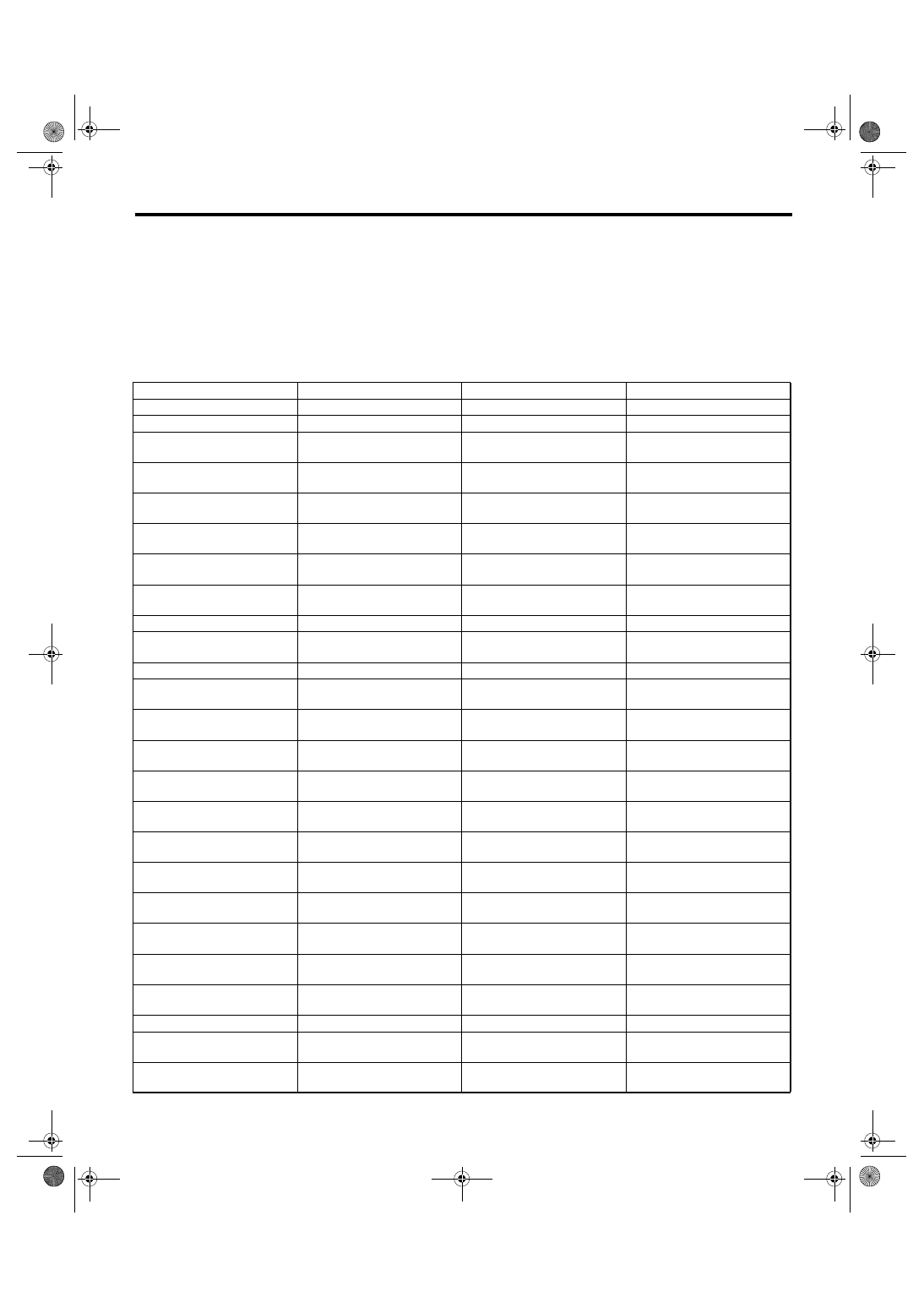
• A list of the support data is shown in the following table.
Remarks
Display
Message
LED “ON” requirements
AT/MT identification signal
AT Vehicle ID Signal
ON or OFF
Illuminate (AT model)
Test mode signal
Test Mode Signal
ON or OFF
D check
Neutral position switch signal
Neutral Position Switch
ON or OFF
When neutral position signal is
entered.
Idle switch signal
Idle Switch Signal
ON or OFF
When idle switch signal is
entered.
Ignition switch signal
Ignition Switch
ON or OFF
When ignition switch is turned
ON.
Power steering switch signal
P/S Switch
ON or OFF
When power steering switch is
entered.
Air conditioning switch signal
A/C Switch
ON or OFF
When air conditioning switch is
input.
Steering wheel switch signal
Handle Switch
RHD or LHD
When handle switch Low sig-
nal is input.
Starter switch signal
Starter Switch
ON or OFF
When starter switch is input.
Rear oxygen sensor rich sig-
nal
Rear O2 Rich Signal
ON or OFF
When rear oxygen sensor mix-
ture ratio is rich.
Knocking signal
Knocking Signal
ON or OFF
When knocking signal is input.
Crankshaft position sensor
signal
Crankshaft Position Sig.
ON or OFF
When crankshaft position sen-
sor signal is input.
Camshaft position sensor sig-
nal
Camshaft Position Sig.
ON or OFF
When camshaft position sen-
sor signal is entered.
Rear defogger switch signal
Rear Defogger Switch
ON or OFF
When rear defogger switch is
turned ON.
Blower fan switch signal
Blower fan SW
ON or OFF
When blower fan switch is
turned ON.
Light switch signal
Light Switch
ON or OFF
When light switch is turned
ON.
Small light switch signal
Light Switch
ON or OFF
When small light switch is
turned ON.
Windshield wiper switch signal
Wiper Switch
ON or OFF
When windshield wiper switch
is turned ON.
A/C middle pressure switch
signal
A/C Mid Pressure Switch
ON or OFF
When A/C middle pressure
switch is turned ON.
Air conditioning relay signal
Compressor relay
ON or OFF
When air conditioning relay is
in function.
Radiator fan relay 1 signal
Radiator Fan Relay #1
ON or OFF
When radiator fan relay 1 is in
function.
Radiator fan relay 2 signal
Radiator Fan Relay #2
ON or OFF
When radiator fan relay 2 is in
function.
Fuel pump relay signal
Fuel Pump Relay
ON or OFF
ON output
AT retard angle demand signal Retard Signal
ON or OFF
When AT retard angle demand
signal is input.
AT fuel cut signal
Fuel Cut
ON or OFF
When AT fuel cut signal is
input.
EN(H4SO 2.0)(diag)-30
ENGINE (DIAGNOSTICS)
Subaru Select Monitor
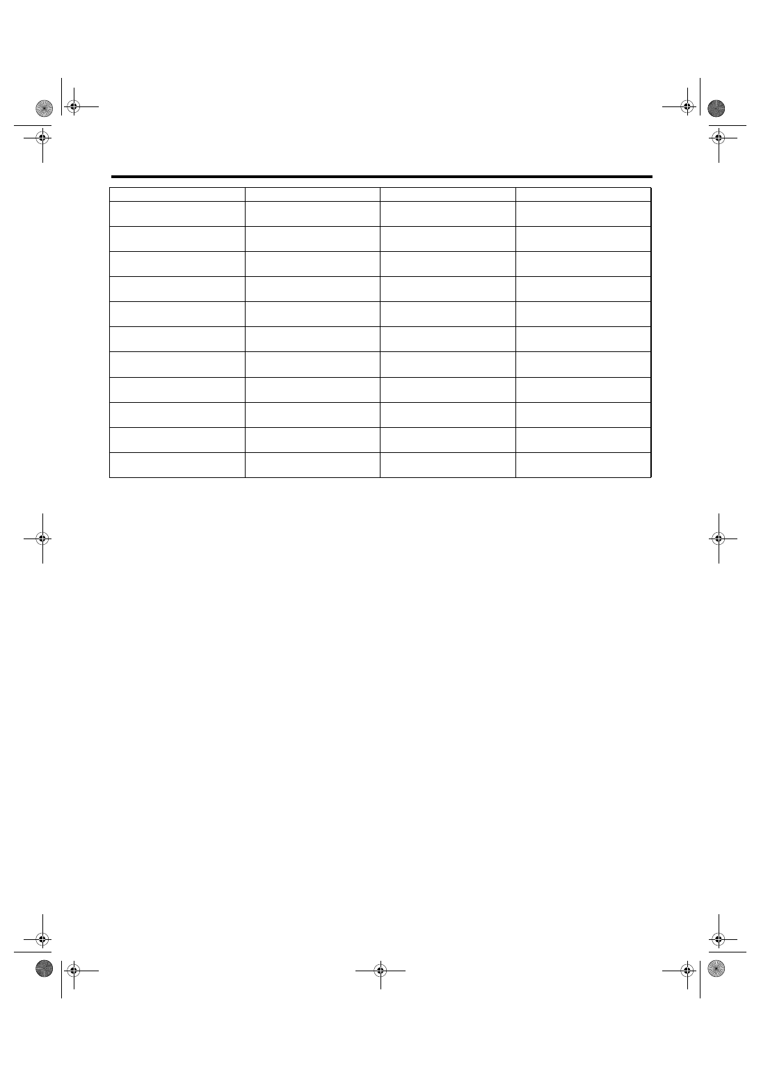
NOTE:
For detailed operation procedure, refer to the SUBARU SELECT MONITOR OPERATION MANUAL.
AT coordinate permission sig-
nal
Torque Permission Signal
ON or OFF
When AT coordinate permis-
sion signal is input.
Clutch switch signal
Clutch Switch
ON or OFF
When clutch switch is turned
to ON.
Stop light switch signal
Stop Light Switch
ON or OFF
When stop light switch is
turned to ON.
SET/COAST switch signal
SET/CST Switch
ON or OFF
When SET/CST switch is
turned to ON.
RESUME/ACCEL switch sig-
nal
RES/ACC Switch
ON or OFF
When RES/ACC switch is
turned to ON.
Brake switch signal
Brake Switch
ON or OFF
When brake switch is turned to
ON.
Main switch signal
Main Switch
ON or OFF
When main switch is turned to
ON.
Cancel switch signal
Cancel Switch
ON or OFF
When cancel switch is turned
to ON.
Electronic throttle control
motor relay signal
ETC Motor Relay
ON or OFF
When electronic throttle con-
trol motor relay is in function.
Data reception signal
Body Int. Unit Data
ON or OFF
When data reception signal is
entered.
Counter update signal
Body Int. Unit Count
ON or OFF
When counter update signal is
entered.
Remarks
Display
Message
LED “ON” requirements
EN(H4SO 2.0)(diag)-31
ENGINE (DIAGNOSTICS)
Read Diagnostic Trouble Code (DTC)
10.Read Diagnostic Trouble
Code (DTC)
A: OPERATION
1. SUBARU SELECT MONITOR (NORMAL
MODE)
1) On the «Main Menu» display screen, select the
{Each System Check} and press the [YES] key.
2) On the «System Selection Menu» display
screen, select the {Engine} and press the [YES]
key.
3) Press the [YES] key after the information of en-
gine type has been displayed.
4) On the «Engine Diagnosis» screen, select the
{Diagnostic Code(s) Display}, and then press the
[YES] key.
5) On the «Diagnostic Code(s) Display» screen,
select the {Current Diagnostic Code(s)} or {History
Diagnostic Code(s)}, and then press the [YES] key.
NOTE:
• For detailed operation procedure, refer to the
SUBARU SELECT MONITOR OPERATION MAN-
UAL.
• For details concerning DTC, refer to “List of Diag-
nostic Trouble Code (DTC)”. <Ref. to EN(H4SO
2.0)(diag)-64, List of Diagnostic Trouble Code
(DTC).>
2. SUBARU SELECT MONITOR (OBD
MODE)
1) On the «Main Menu» display screen, select the
{Each System Check} and press the [YES] key.
2) On the «System Selection Menu» display
screen, select the {Engine} and press the [YES]
key.
3) Press the [YES] key after the information of en-
gine type has been displayed.
4) On the «Engine Diagnosis» display screen, se-
lect the {OBD System} and press the [YES] key.
5) On the «OBD Menu» display screen, select the
{Diagnostic Code(s) Display} and press the [YES]
key.
6) Make sure DTC is shown on the screen.
NOTE:
• For detailed operation procedure, refer to the
SUBARU SELECT MONITOR OPERATION MAN-
UAL.
• For details concerning DTC, refer to “List of Diag-
nostic Trouble Code (DTC)”. <Ref. to EN(H4SO
2.0)(diag)-64, List of Diagnostic Trouble Code
(DTC).>
3. GENERAL SCAN TOOL
Refer to the data denoting emission-related power-
train DTC.
For details concerning DTC, refer to “List of Diag-
nostic Trouble Code (DTC)”. <Ref. to EN(H4SO
2.0)(diag)-64, List of Diagnostic Trouble Code
(DTC).>
NOTE:
Refer to the general scan tool manufacturer’s oper-
ation manual to access powertrain DTC (MODE
$03).
EN(H4SO 2.0)(diag)-32
ENGINE (DIAGNOSTICS)
Inspection Mode
11.Inspection Mode
A: PROCEDURE
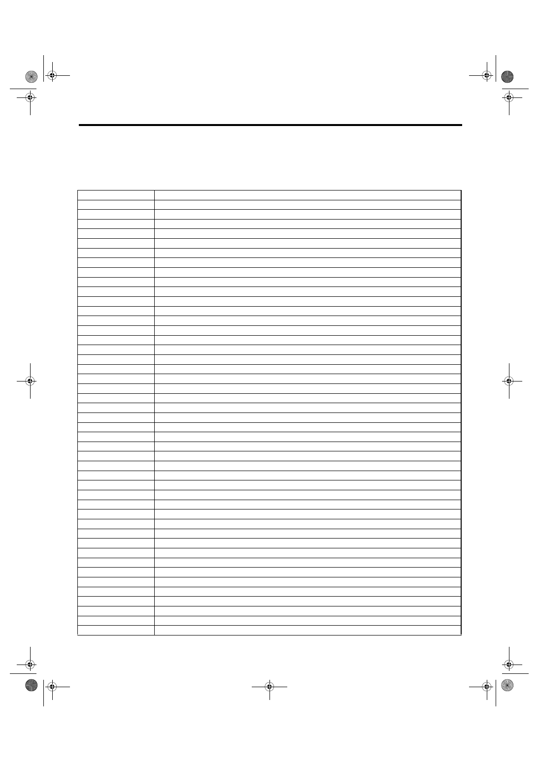
Carry out trouble diagnosis shown in the following DTC table.
When performing trouble diagnosis which is not shown in the DTC table, refer to the next item Drive cycle.
<Ref. to EN(H4SO 2.0)(diag)-31, Read Diagnostic Trouble Code (DTC).>
DTC
Item
P0031
HO2S Heater Control Circuit Low (Bank 1 Sensor 1)
P0032
HO2S Heater Control Circuit High (Bank 1 Sensor 1)
P0037
HO2S Heater Control Circuit Low (Bank 1 Sensor 2)
P0038
HO2S Heater Control Circuit High (Bank 1 Sensor 2)
P0107
Manifold Absolute Pressure/Barometric Pressure Circuit Low Input
P0108
Manifold Absolute Pressure/Barometric Pressure Circuit High Input
P0112
Intake Air Temperature Sensor 1 Circuit Low
P0113
Intake Air Temperature Sensor 1 Circuit High
P0117
Engine Coolant Temperature Circuit Low
P0118
Engine Coolant Temperature Circuit High
P0122
Throttle/Pedal Position Sensor/Switch “A” Circuit Low
P0123
Throttle/Pedal Position Sensor/Switch “A” Circuit High
P0131
O2 Sensor Circuit Low Voltage (Bank 1 Sensor 1)
P0132
O2 Sensor Circuit High Voltage (Bank 1 Sensor 1)
P0134
O2 Sensor Circuit No Activity Detected (Bank 1 Sensor 1)
P0137
O2 Sensor Circuit Low Voltage (Bank 1 Sensor 2)
P0138
O2 Sensor Circuit High Voltage (Bank 1 Sensor 2)
P0222
Throttle/Pedal Position Sensor/Switch “B” Circuit Low
P0223
Throttle/Pedal Position Sensor/Switch “B” Circuit High
P0327
Knock Sensor 1 Circuit Low (Bank 1 or Single Sensor)
P0328
Knock Sensor 1 Circuit High (Bank 1 or Single Sensor)
P0335
Crankshaft Position Sensor “A” Circuit
P0340
Camshaft Position Sensor “A” Circuit (Bank 1 or Single Sensor)
P0458
Evaporative Emission System Purge Control Valve Circuit Low
P0459
Evaporative Emission System Purge Control Valve Circuit High
P0462
Fuel Level Sensor “A” Circuit Low
P0463
Fuel Level Sensor “A” Circuit High
P0500
Vehicle Speed Sensor “A”
P0512
Starter Request Circuit
P0513
Incorrect Immobilizer Key
P0519
Idle Air Control System Performance
P0600
Serial Communication Link
P0604
Internal Control Module Random Access Memory (RAM) Error
P0605
Internal Control Module Read Only Memory (ROM) Error
P0607
Control Module Performance
P0638
Throttle Actuator Control Range/Performance (Bank 1)
P0691
Fan 1 Control Circuit Low
P0692
Fan 1 Control Circuit High
P0851
Park/Neutral Switch Input Circuit Low
P0852
Park/Neutral Switch Input Circuit High
P1134
A/F Sensor Micro-Computer Problem
P1160
Return Spring Failure
P1518
Starter Switch Circuit Low Input
P1560
Back-up Voltage Circuit Malfunction
P1570
Antenna
Нет комментариевНе стесняйтесь поделиться с нами вашим ценным мнением.
Текст