Subaru Legacy (2005 year). Service manual — part 112
EN(H4SO 2.0)(diag)-37
ENGINE (DIAGNOSTICS)
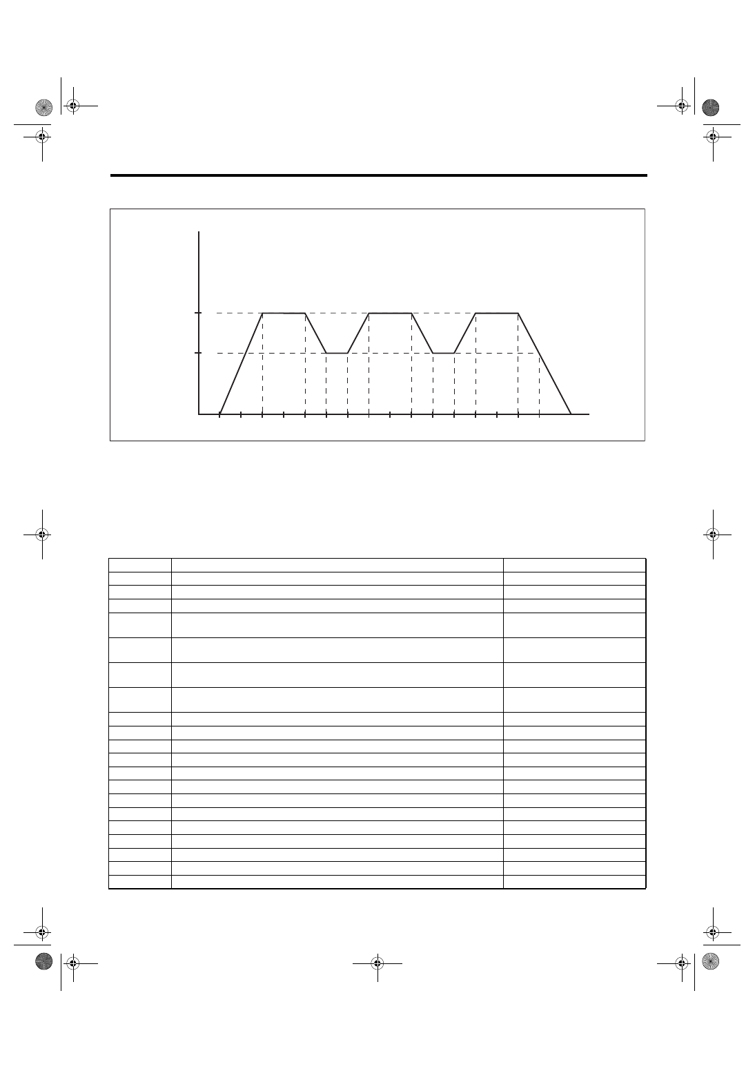
Drive Cycle
3. DRIVE ACCORDING TO THE FOLLOWING DRIVE PATTERN
(A)
Idle engine for 1 minute.
(E)
Drive the vehicle at 65 km/h (40
MPH) for 10 seconds.
(G)
Stop vehicle with throttle fully
closed.
(B)
Accelerate the vehicle to 96 km/h
(60 MPH) within 20 seconds.
(F)
Accelerate the vehicle to 96 km/h
(60 MPH) within 10 seconds.
(H)
Vehicle speed km/h (MPH)
(C)
Drive the vehicle at 96 km/h (60
MPH) for 20 seconds.
(I)
Sec.
(D)
Decelerate the vehicle to 65 km/h
(40 MPH) with throttle fully closed.
DTC
Item
Condition
*P0030
HO2S Heater Control Circuit (Bank 1 Sensor 1)
—
P0130
O2 Sensor Circuit (Bank1 Sensor1)
—
*P0139
O2 Sensor Circuit Slow Response (Bank 1 Sensor 2)
—
P0301
Cylinder 1 Misfire Detected
Diagnosis frequency is different
from misfire ratio.
P0302
Cylinder 2 Misfire Detected
Diagnosis frequency is different
from misfire ratio.
P0303
Cylinder 3 Misfire Detected
Diagnosis frequency is different
from misfire ratio.
P0304
Cylinder 4 Misfire Detected
Diagnosis frequency is different
from misfire ratio.
P0400
Exhaust Gas Recirculation Flow
—
P0700
Transmission Control System (MIL Request)
—
P1134
A/F Sensor Micro-Computer Problem
—
P1492
EGR Solenoid Valve Signal #1 Circuit Malfunction (Low Input)
—
P1493
EGR Solenoid Valve Signal #1 Circuit Malfunction (High Input)
—
P1494
EGR Solenoid Valve Signal #2 Circuit Malfunction (Low Input)
—
P1495
EGR Solenoid Valve Signal #2 Circuit Malfunction (High Input)
—
P1496
EGR Solenoid Valve Signal #3 Circuit Malfunction (Low Input)
—
P1497
EGR Solenoid Valve Signal #3 Circuit Malfunction (High Input)
—
P1498
EGR Solenoid Valve Signal #4 Circuit Malfunction (Low Input)
—
P1499
EGR Solenoid Valve Signal #4 Circuit Malfunction (High Input)
—
P1521
Brake Switch Circuit Range/Performance Problem (High Input)
—
P2504
Charging System Voltage High
—
50
100
150
0
65 (40)
96 (60)
(I)
(H)
(A)
(B)
(C)
(D)
(E)
(F)
(G)
EN-00195
EN(H4SO 2.0)(diag)-38
ENGINE (DIAGNOSTICS)
Clear Memory Mode
13.Clear Memory Mode
A: OPERATION
1. SUBARU SELECT MONITOR (NORMAL
MODE)
1) On the «Main Menu» display screen, select the
{Each System Check} and press the [YES] key.
2) On the «System Selection Menu» display
screen, select the {Engine} and press the [YES]
key.
3) Press the [YES] key after the information of en-
gine type has been displayed.
4) On the «Engine Diagnosis» display screen, se-
lect the {Clear Memory} and press the [YES] key.
5) When the “Done” and “Turn Ignition Switch OFF”
are shown on the display screen, turn the ignition
switch to OFF and then Subaru Select Monitor
power switch to OFF.
NOTE:
• Initial diagnosis of electronic throttle control is
performed after memory clearance. For this rea-
son, start the engine after 10 seconds or more have
elapsed since the ignition switch was turned to ON.
• For detailed operation procedure, refer to the
SUBARU SELECT MONITOR OPERATION MAN-
UAL.
2. SUBARU SELECT MONITOR (OBD
MODE)
1) On the «Main Menu» display screen, select the
{Each System Check} and press the [YES] key.
2) On the «System Selection Menu» display
screen, select the {Engine} and press the [YES]
key.
3) Press the [YES] key after the information of en-
gine type has been displayed.
4) On the «Engine Diagnosis» display screen, se-
lect the {OBD System} and press the [YES] key.
5) On the «OBD Menu» display screen, select the
{DTC Clear} and press the [YES] key.
6) When the “Clear Diagnostic Code?” is shown on
the screen, press the [YES] key.
7) Turn the ignition switch to OFF, and the Subaru
Select Monitor power switch to OFF.
NOTE:
• Initial diagnosis of electronic throttle control is
performed after memory clearance. For this rea-
son, start the engine after 10 seconds or more have
elapsed since the ignition switch was turned to ON.
• For detailed operation procedure, refer to the
SUBARU SELECT MONITOR OPERATION MAN-
UAL.
3. GENERAL SCAN TOOL
For clear memory procedures using the general
scan tool, refer to the general scan tool operation
manual.
EN(H4SO 2.0)(diag)-39
ENGINE (DIAGNOSTICS)
Compulsory Valve Operation Check Mode
14.Compulsory Valve Operation
Check Mode
A: PROCEDURE
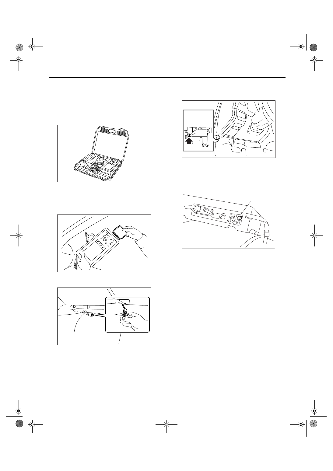
1) Prepare the Subaru Select Monitor kit. <Ref. to
EN(H4SO 2.0)(diag)-7, PREPARATION TOOL,
General Description.>
2) Connect the diagnosis cable to Subaru Select
Monitor.
3) Insert the cartridge to Subaru Select Monitor.
<Ref. to EN(H4SO 2.0)(diag)-7, PREPARATION
TOOL, General Description.>
4) Connect the test mode connector (A) in the low-
er portion of glove box.
5) Connect the Subaru Select Monitor to data link
connector located in the lower portion of the instru-
ment panel (on the driver’s side).
CAUTION:
Do not connect any scan tools except Subaru
Select Monitor or general scan tool.
6) Turn the ignition switch to ON (engine OFF), and
the Subaru Select Monitor power switch to ON.
7) On the «Main Menu» display screen, select the
{Each System Check} and press the [YES] key.
8) On the «System Selection Menu» display
screen, select the {Engine} and press the [YES]
key.
9) Press the [YES] key after the information of en-
gine type has been displayed.
10) On the «Engine Diagnosis» display screen, se-
lect the {System Operation Check Mode} and press
the [YES] key.
11) On the «System Operation Check Mode» dis-
play screen, select the {Actuator ON/OFF Opera-
tion} and press the [YES] key.
12) Select the desired actuator on the «Actuator
ON/OFF Operation» display screen and press the
[YES] key.
EN-00038
EN-00039
PI-00201
(A)
(A) Power switch
EN-02533
(A)
EN-00040
EN(H4SO 2.0)(diag)-40
ENGINE (DIAGNOSTICS)
Compulsory Valve Operation Check Mode
13) Pressing the [NO] key completes the compul-
sory valve operation check mode. The display will
then return to the «Actuator ON/OFF Operation»
screen.
• A list of the support data is shown in the following
table.
NOTE:
• The following parts will be displayed but not func-
tional.
• For detailed operation procedure, refer to the
SUBARU SELECT MONITOR OPERATION MAN-
UAL.
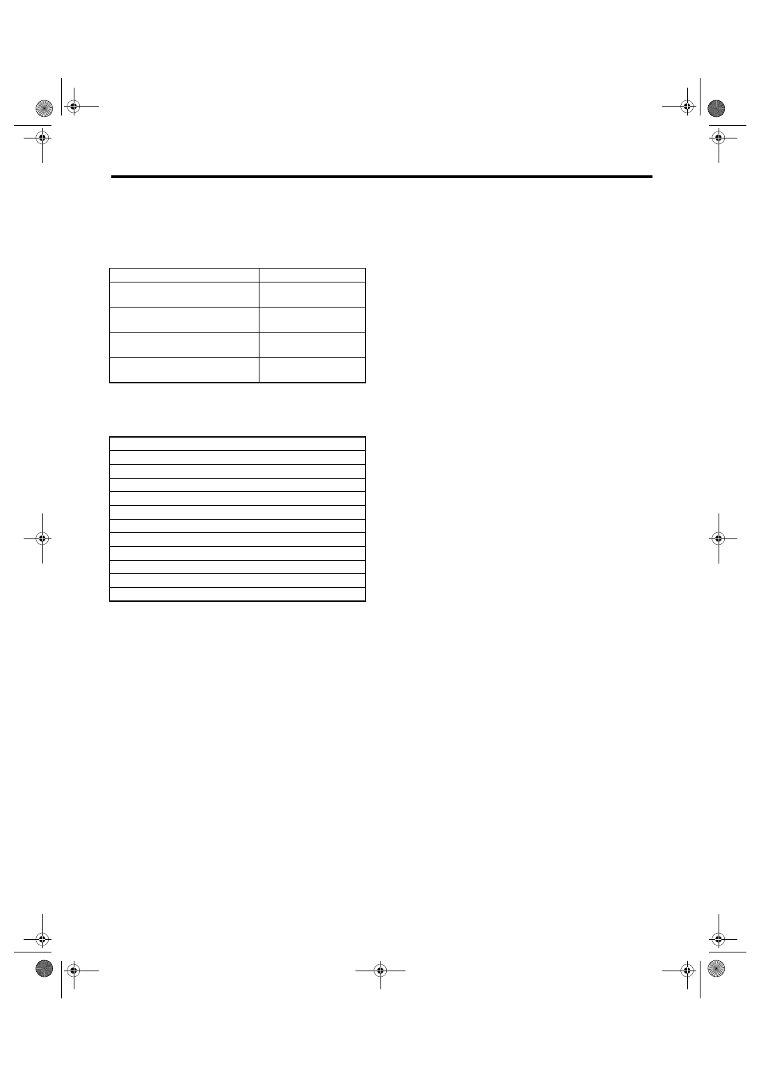
DESCRIPTION
Display
Compulsory fuel pump relay oper-
ation check
Fuel Pump
Compulsory radiator fan relay
operation check
Radiator Fan Relay
Compulsory air conditioning relay
operation check
A/C Compressor Relay
Compulsory purge control sole-
noid valve operation check
CPC Solenoid Valve
Display
EGR Solenoid Valve
ASV Solenoid Valve
FICD Solenoid
Pressure Switching Sol.1
Pressure Switching Sol.2
Turbocharger Wastegate Solenoid
PCV Solenoid Valve
Vent. Solenoid Valve
AAI Solenoid Valve
Tank Sensor Cntl Valve
Exhaust Bypass Valve Control Permit Flag
Нет комментариевНе стесняйтесь поделиться с нами вашим ценным мнением.
Текст