Subaru Legacy (2005 year). Service manual — part 109
EN(H4SO 2.0)(diag)-25
ENGINE (DIAGNOSTICS)
Subaru Select Monitor
9. Subaru Select Monitor
A: OPERATION
1. HOW TO USE SUBARU SELECT MONI-
TOR
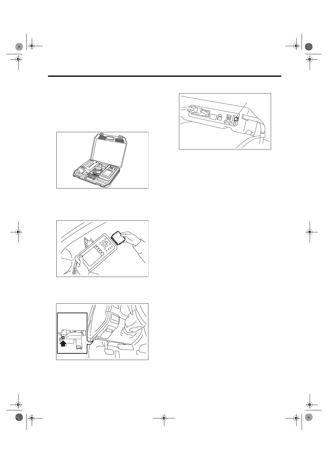
1) Prepare the Subaru Select Monitor kit. <Ref. to
EN(H4SO 2.0)(diag)-7, PREPARATION TOOL,
General Description.>
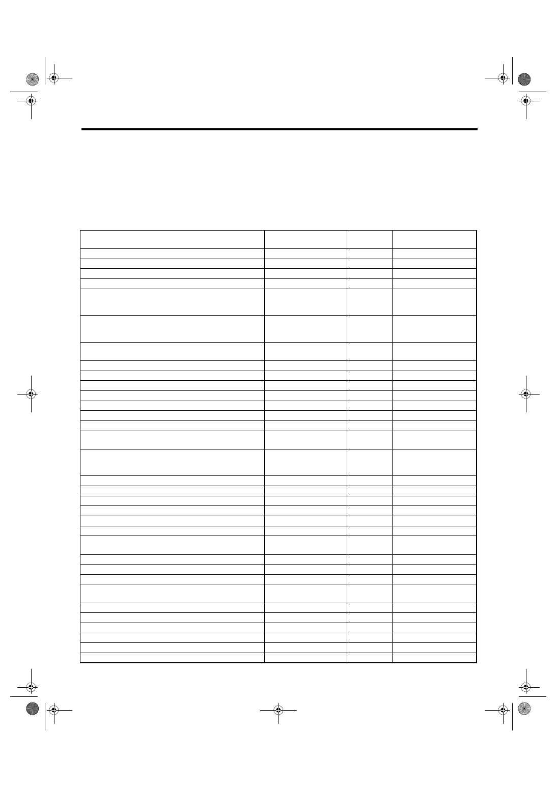
2) Connect the diagnosis cable to Subaru Select
Monitor.
3) Insert the cartridge to Subaru Select Monitor.
<Ref. to EN(H4SO 2.0)(diag)-7, PREPARATION
TOOL, General Description.>
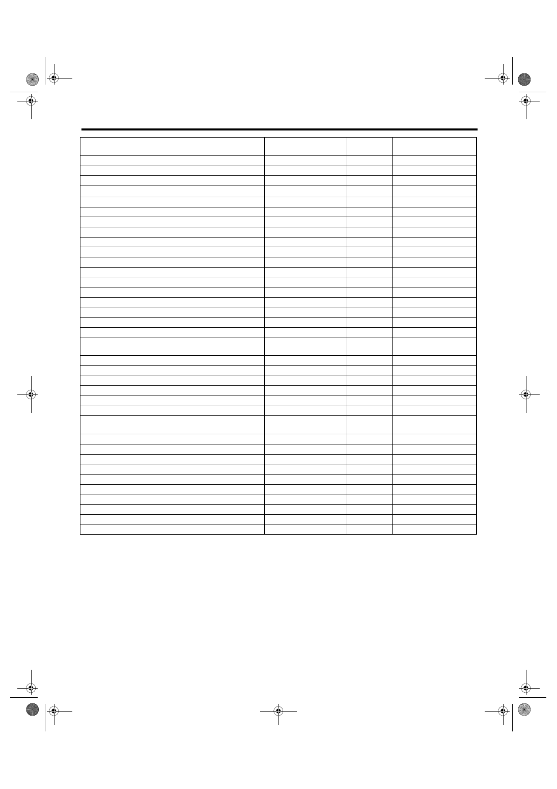
4) Connect the Subaru Select Monitor to data link
connector.
(1) Data link connector is located in the lower
portion of instrument panel (on the driver’s side).
(2) Connect the diagnosis cable to data link
connector.
CAUTION:
Do not connect any scan tools except Subaru
Select Monitor or general scan tool.
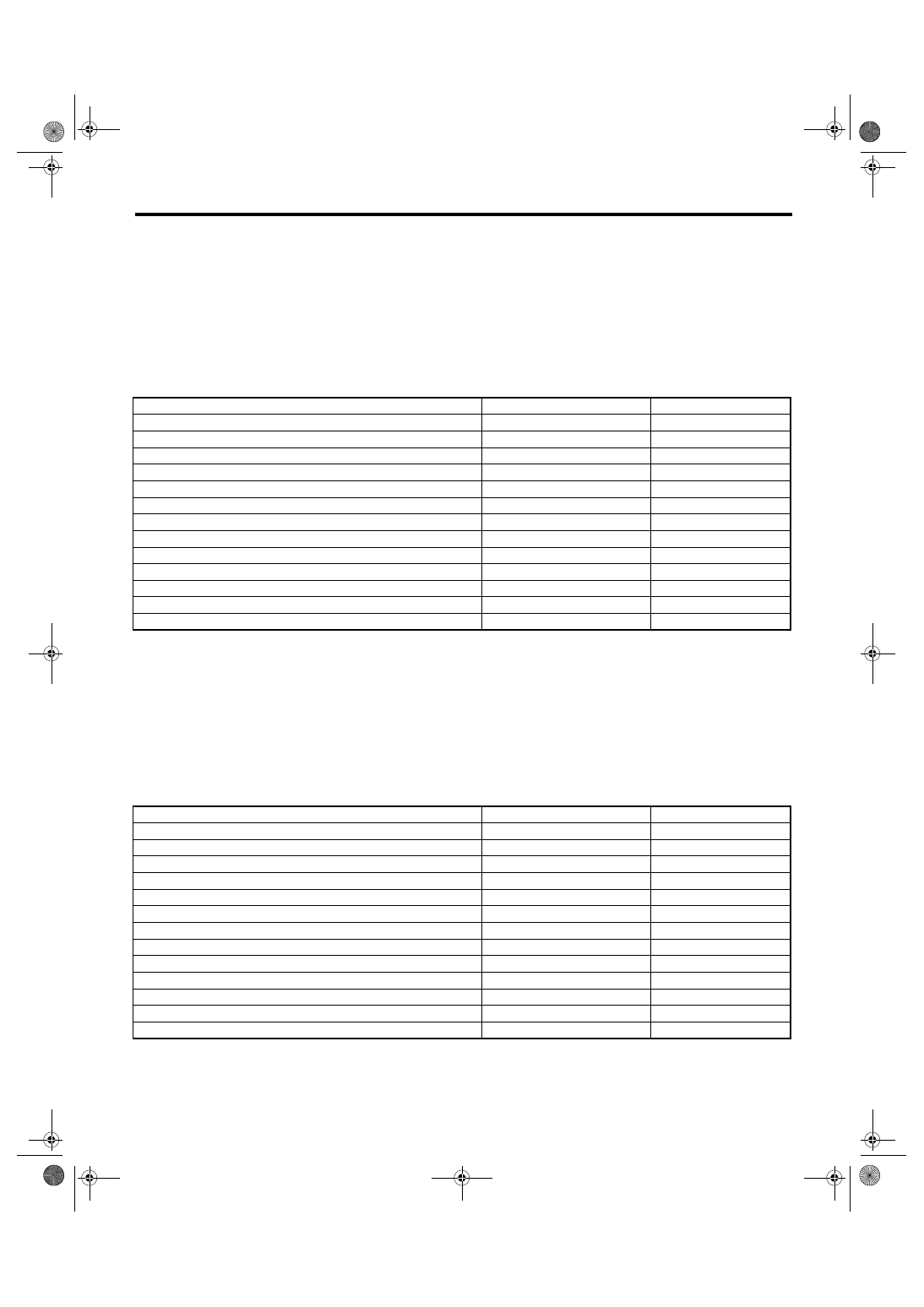
5) Turn the ignition switch to ON (engine OFF), and
the Subaru Select Monitor power switch to ON.
6) Using the Subaru Select Monitor, call up DTC
and data, then record them.
2. READ DIAGNOSTIC TROUBLE CODE
(DTC) FOR ENGINE (NORMAL MODE)
Refer to “Read Diagnostic Trouble Code (DTC)” for
information about how to indicate DTCs. <Ref. to
EN(H4SO 2.0)(diag)-31, Read Diagnostic Trouble
Code (DTC).>
3. READ DIAGNOSTIC TROUBLE CODE
(DTC) FOR ENGINE (OBD MODE)
Refer to “Read Diagnostic Trouble Code (DTC)” for
information about how to indicate DTCs. <Ref. to
EN(H4SO 2.0)(diag)-31, Read Diagnostic Trouble
Code (DTC).>
EN-00038
EN-00039
EN-02533
(A) Power switch
(A)
EN-00040
EN(H4SO 2.0)(diag)-26
ENGINE (DIAGNOSTICS)
Subaru Select Monitor
4. READ CURRENT DATA FOR ENGINE. (NORMAL MODE)
1) On the «Main Menu» display screen, select the {Each System Check} and press the [YES] key.
2) On the «System Selection Menu» display screen, select the {Engine} and press the [YES] key.
3) Press the [YES] key after the information of engine type has been displayed.
4) On the «Engine Diagnosis» display screen, select the {Current Data Display & Save}, and then press the
[YES] key.
5) On the «Data Display Menu» screen, select the {Data Display} and press the [YES] key.
6) Using the scroll key, move the display screen up or down until the desired data is shown.
• A list of the support data is shown in the following table.
Remarks
Display
Unit of mea-
sure
Note (at idling)
Engine load
Engine load
%
1 — 3%
Engine coolant temperature signal
Coolant Temp.
°C or °F
≥ 75 °C or 167°F
A/F Correction #1
A/F Correction #1
%
−10 — +10%
A/F Learning #1
A/F Learning #1
%
−15 — +15%
Intake manifold absolute pressure
Mani. Absolute Pressure
mmHg, kPa,
inHg or psig
200 — 300 mmHg, 26.7
— 40 kPa, 7.8 — 11.8
inHg or 3.8 — 5.8 psig
Engine speed signal
Engine Speed
rpm
600 — 800 rpm (Agree
with the tachometer indi-
cation)
Meter vehicle speed signal
Vehicle Speed
km/h or
MPH
0 km/h or 0 MPH
(at parking)
Ignition timing signal
Ignition Timing
deg
10 — 15 deg
Intake air temperature signal
Intake Air Temp.
°C or °F
(Ambient air temperature)
Throttle opening angle signal
Throttle Opening Angle
%
1 — 2%
Rear oxygen sensor voltage
Rear O2 Sensor
V
0.01 — 0.85 V
Battery voltage
Battery Voltage
V
12 — 14 V
Injection 1 pulse width
Fuel Injection #1 Pulse
ms
2 — 4 ms
Knock sensor correction
Knocking Correction
deg
0.0 deg
Atmospheric pressure signal
Atmosphere Pressure
mmHg, kPa,
inHg or psig
(Atmosphere pressure)
Intake manifold relative pressure
Mani. Relative Pressure
mmHg, kPa,
inHg or psig
(Intake manifold absolute
pressure
− Atmospheric
pressure)
Learned Ignition Timing
Learned Ignition Timing
°
−2 — 2°
Acceleration opening angle signal
Accel. Opening Angle
%
0.0%
Rear oxygen sensor heater current
Rear O2 Heater Current
A
0.9 — 1.1 A
Purge control solenoid duty ratio
CPC Valve Duty Ratio
%
0 — 3%
EGR step number
EGR step number
STEP
0
Generator duty ratio
ALT Duty
%
0 — 100%
A/F sensor resistance value 1
A/F Sensor #1 Resis-
tance
Ω
25 — 27 mA
A/F sensor output lambda 1
A/F Sensor #1
—
0.85 — 1.15
A/F correction 3
A/F Correction #3
%
3.5 — 6.5%
Front oxygen (A/F) sensor current
A/F Heater Current
A
5 — 10 A
Main-throttle position sensor fully closed voltage
Main-Throttle Sensor
Closed Position Voltage
V
0.3 — 0.7 V
AT/MT identification terminal
AT Vehicle ID Signal
—
ON/OFF
Test mode terminal
Test Mode Signal
—
OFF
Neutral position switch signal
Neutral Position Switch
—
ON
Soft idle switch signal
Idle Switch Signal
—
ON
Ignition switch signal
Ignition Switch
—
ON
Power steering switch signal
P/S Switch
—
OFF (At OFF)
EN(H4SO 2.0)(diag)-27
ENGINE (DIAGNOSTICS)
Subaru Select Monitor
NOTE:
For detailed operation procedure, refer to the SUBARU SELECT MONITOR OPERATION MANUAL.
Air conditioning switch signal
A/C Switch
—
OFF (At OFF)
Steering wheel switch signal
Handle Switch
—
Hi/Low
Starter switch signal
Starter Switch
—
OFF
Rear O
2
monitor
Rear O2 Rich Signal
—
Rich/Lean
Knocking signal
Knocking Signal
—
OFF
Crankshaft position sensor signal
Crankshaft Position Sig.
—
OFF
Camshaft position sensor signal
Camshaft Position Sig.
—
OFF
Rear defogger switch signal
Rear defogger SW
—
OFF (At OFF)
Blower fan switch signal
Blower Fan SW
—
OFF (At OFF)
Light switch signal
Light Switch
—
OFF (At OFF)
Wiper switch signal
Wiper Switch
—
OFF (At OFF)
A/C middle pressure switch signal
A/C Mid Pressure Switch
—
OFF (At OFF)
Air conditioner compressor relay output signal
A/C Compressor Signal
—
OFF (At OFF)
Radiator fan relay 1 signal
Radiator Fan Relay #1
—
OFF (At OFF)
Radiator fan relay 2 signal
Radiator Fan Relay #2
—
OFF (At OFF)
Fuel pump relay signal
Fuel Pump Relay
—
ON
AT coordinate retard angle demand signal
Retard Signal from AT
—
OFF
AT coordinate fuel cut demand signal
Fuel Cut Signal from AT
—
OFF
AT coordinate permission signal
Torque Permission Sig-
nal
—
ON/OFF
Throttle motor duty
Throttle Motor Duty
%
5 — 10%
Throttle power supply voltage
Throttle Motor Voltage
V
(Battery voltage)
Sub throttle sensor voltage
Sub-Throttle Sensor
V
1.48 — 1.50 V
Main throttle sensor voltage
Main-throttle Sensor
V
0.62 V
Sub acceleration sensor voltage
Sub-Accelerator Sensor
V
0.5 — 1.5 V
Main acceleration sensor voltage
Main-Accelerator Sensor
V
0.5 — 1.5 V
Memory vehicle speed
Memorized Cruise
Speed
km/h or
MPH
0 km/h or 0 MPH
Fuel level sensor resistance
Fuel level resistance
Ω
0 — 100
Ω
ETC motor relay signal
ETC Motor Relay
—
ON
Clutch switch signal
Clutch Switch
—
OFF (At OFF)
Stop light switch signal
Stop Light Switch
—
OFF (At OFF)
SET/COAST switch signal
SET/CST Switch
—
OFF (At OFF)
RESUME/ACCEL switch signal
RES/ACC Switch
—
OFF (At OFF)
Brake switch signal
Brake Switch
—
OFF (At OFF)
Main switch signal
Main Switch
—
OFF (At OFF)
Integrated module data reception
Body Int. Unit Data
—
ON
Integrated module data update
Body Int. Unit Count
—
ON
Remarks
Display
Unit of mea-
sure
Note (at idling)
EN(H4SO 2.0)(diag)-28
ENGINE (DIAGNOSTICS)
Subaru Select Monitor
5. READ CURRENT DATA FOR ENGINE (OBD MODE)
1) On the «Main Menu» display screen, select the {Each System Check} and press the [YES] key.
2) On the «System Selection Menu» display screen, select the {Engine} and press the [YES] key.
3) Press the [YES] key after the information of engine type has been displayed.
4) On the «Engine Diagnosis» display screen, select the {OBD System} and press the [YES] key.
5) On the «OBD Menu» display screen, select the {Current Data Display & Save}, and then press the [YES]
key.
6) On the «Data Display Menu» screen, select the {Data Display} and press the [YES] key.
7) Using the scroll key, move the display screen up or down until the desired data is shown.
• A list of the support data is shown in the following table.
NOTE:
For detailed operation procedure, refer to the SUBARU SELECT MONITOR OPERATION MANUAL.
6. READ FREEZE FRAME DATA FOR ENGINE. (OBD MODE)
1) On the «Main Menu» display screen, select the {Each System Check} and press the [YES] key.
2) On the «System Selection Menu» display screen, select the {Engine} and press the [YES] key.
3) Press the [YES] key after the information of engine type has been displayed.
4) On the «Engine Diagnosis» display screen, select the {OBD System} and press the [YES] key.
5) On the «OBD Menu» display screen, select the {Freeze Frame Data} and press the [YES] key.
• A list of the support data is shown in the following table.
NOTE:
For detailed operation procedure, refer to the SUBARU SELECT MONITOR OPERATION MANUAL.
DESCRIPTION
Display
Unit of measure
Number of diagnosis code
Number of Diagnostic Code(s):
0
Condition of malfunction indicator light
MI (MIL)
OFF
Monitoring test of misfire
Misfire monitoring
—
Monitoring test of fuel system
Fuel system monitoring
complete
Monitoring test of comprehensive component
Component monitoring
complete
Test of catalyst
Catalyst Diagnosis
—
Test of heating-type catalyst
Heated catalyst
no support
Test of evaporative emission purge control system
Evaporative purge system
no support
Test of secondary air system
Secondary air system
no support
Test of air conditioning system refrigerant
A/C system refrigerant
no support
Test of oxygen sensor
Oxygen sensor
complete
Test of oxygen sensor heater
O2 Heater Diagnosis
complete
Test of EGR system
EGR system
complete
DESCRIPTION
Display
Unit of measure
DTC for freeze frame data
Freeze frame data
DTC
Air fuel ratio control system for bank 1
Fuel system for Bank1
—
Engine load data
Engine Load
%
Engine coolant temperature signal
Coolant Temp.
°C or °F
Short term fuel trim by front oxygen (A/F) sensor
Short term fuel trim B1
%
Long term fuel trim by front oxygen (A/F) sensor
Long term fuel trim B1
%
Intake manifold absolute pressure signal
Mani. Absolute Pressure
mmHg, kPa, inHg or psig
Engine speed signal
Engine Speed
rpm
Vehicle speed signal
Vehicle Speed
km/h or MPH
Ignition timing signal
Ignition Timing
°
Amount of intake air
Mass Air Flow
g/s or lb/m
Intake air temperature signal
Intake Air Temp
°C or °F
Throttle position signal
Throttle Opening Angle
%
Нет комментариевНе стесняйтесь поделиться с нами вашим ценным мнением.
Текст